Advertisement
Quick Links
ADULT ASSEMBLY REQUIRED DUE TO THE PRESENCE OF SMALL PARTS, SHARP
POINTS, SHARP EDGES AS RECEIVED
If you have any questions regarding assembly or if parts are missing, DO NOT return this item to the
store where it was purchased. Please call our toll-free customer service number and have your
instructions and parts list ready to provide the model name, part name or factory number:
Pacific Standard Time: 8:30 a.m. - 4:30 p.m., Monday - Friday
Or visit our web site 24 hours a day, 7 days a week for product assistance at
THIS INSTRUCTION BOOKLET CONTAINS IMPORTANT SAFETY INFORMATION.
Thomasville™ is a trademark of HHG IPCo, LLC. ©HHG IPCo, LLC. thomasville.com
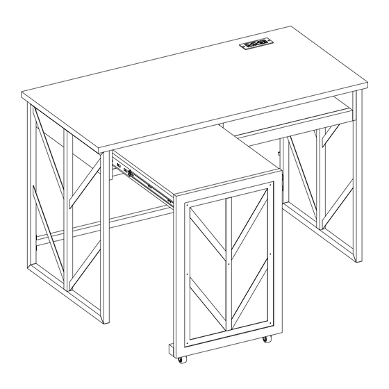
Azuria L Desk
Model # SPCA-AZRLD-TV
1-866-942-5362
www.whalenfurniture.com
Or e-mail your request to parts@whalenfurniture.com
PLEASE READ AND KEEP FOR FUTURE REFERENCE.
Date 2023-11-29
LOT NUMBER:
DATE PURCHASED: /
Rev. 0001-A
/
Advertisement

Subscribe to Our Youtube Channel
Related Manuals for Thomasville Azuria SPCA-AZRLD-TV


Summary of Contents for Thomasville Azuria SPCA-AZRLD-TV
- Page 1 Or visit our web site 24 hours a day, 7 days a week for product assistance at www.whalenfurniture.com Or e-mail your request to parts@whalenfurniture.com THIS INSTRUCTION BOOKLET CONTAINS IMPORTANT SAFETY INFORMATION. PLEASE READ AND KEEP FOR FUTURE REFERENCE. Date 2023-11-29 Rev. 0001-A Thomasville™ is a trademark of HHG IPCo, LLC. ©HHG IPCo, LLC. thomasville.com...
-
Page 2: Special Note
M A X I M U M R E C O M M E N D E D W E I G H T L O A D S MANUFACTURER: Whalen Furniture Manufacturing CATALOG: Azuria L Desk MODEL # SPCA-AZRLD-TV MAXIMUM LOAD 90.7 kg / 200 lb. - Page 3 IMPORTANT Before you begin: Open, identify and count all parts prior to assembly. Lay out parts on a flat and non- abrasive surface. You will need the parts identified on page 6 and 7 of this instruction manuals. NOTE: IT IS VERY IMPORTANT TO USE GLUE WITH DOWELS. EXCESS GLUE CAN BE WIPED OFF WITH DAMP CLOTH.
- Page 4 FURNITURE POWER DISTRIBUTION CENTER IMPORTANT SAFETY INSTRUCTIONS Carefully read all instructions installing and operating fixture IF YOU HAVE ANY QUESTIONS REGARDING THE PROPER INSTALLATION CONSULT A QUALIFIED ELECTRICIAN. TO REDUCE THE RISK OF FIRE, ELECTRICAL SHOCK OR INJURY TO PERSONS, PLEASE FOLLOW THE NEXT: ...
-
Page 5: Specifications
Furniture Power Distribution Unit User Guide Please read this user guide before installing and using your power distribution Center. INTRODUCTION The integrated power and USB center can connect to two devices, such as a digital camera, MP3 player, tablet or cell phone. - Page 6 Parts and Hardware List Please read completely through the instructions and verify that all listed parts and hardware are present before beginning assembly. A- Desk Top B- Fixed Shelf C- Left Apron (Qty. 1) (Qty. 1) (Qty. 1) D- Right Apron E- Partition Panel F- Right Front Molding (Qty.
- Page 7 Parts and Hardware List Please read completely through the instructions and verify that all listed parts and hardware are present before beginning assembly. P- Metal Frame Q- Bottom Stretcher R- Power Center (Qty. 1) (Qty. 1) (Qty. 1) S- Metal Bracket (1) Cam Lock (2) Cam Bolt (Qty.
- Page 8 Assembly Instructions 1. Unpack the unit and confirm that you have all the hardware and required parts listed. Assemble the unit on a carpeted floor or the empty carton to avoid any scratch. 2. Securely screw the Cam Bolts (2) into the plastic inserts on Desk Top (A) and Right Front Molding (F). NOTE: Screw-in cam bolts must be screwed down flush.
- Page 9 Assembly Instructions DO NOT fully tighten the bolts or screws initially until all the bolts or screws are ready to assemble. To avoid causing damages to the thread, DO NOT over-tighten the bolts or screws. 4. Align and attach Left Apron (C) to the Left Side Frame (N) with four 25 mm Bolts (9). 5.
- Page 10 Assembly Instructions The cam lock housings face inward and are located at upper end 6. Orient and position the Back Apron (G) as shown so that the Cam Bolts installed on Right Apron (D) enter the cross holes at right end of the Back Apron. Make sure that the cam lock housings for Desk Top (A) face inward and are located at upper end.
- Page 11 Assembly Instructions The cam lock housings are located at upper end 9. Orient and attach the Partition Panel (E) to the Back Apron (G) by engaging two Cam Locks (1) as shown. Turn the Cam Locks with a Phillips screwdriver until securely locked onto the Cam Bolts. 10.
- Page 12 Assembly Instructions 12. Insert four 40 mm Bolts (11) through the mounting holes on the top rails of both Side Frames (N and O) and securely screw into the Desk Top (A). Tighten the bolts with the hex wrench provided. The threaded inserts for Metal Frame (P) 13.
- Page 13 Assembly Instructions 14. Using the pilot holes as a guide, orient and fasten the Metal Frame (P) to the Fixed Shelf (B) with ten 38 mm Screws (7). Make sure that the mounting holes on the front rail of Metal Frame (P) overlap the threaded inserts on the Right Front Molding (F) properly.
- Page 14 Assembly Instructions 16. Orient and slide the assembled Fixed Shelf (B) between Left and Right Aprons (C and D). You may need to loosen the fasteners on both Side Frames (N and O) and Back Apron (G) and then push or pull them slightly so that the mounting holes on Metal Frame (P) overlap the threaded inserts in the Left and Right Aprons (C and D) properly.
- Page 15 Assembly Instructions 19. Align and attach the Bottom Stretcher (Q) between Left and Right Side Frames (N and O) with four 15 mm Bolts (8). Tighten the bolts with the hex wrench provided. 20. Go back and tighten all the fasteners. Now, ask for assistance to lift the unit upright and position it near the final location.
- Page 16 Assembly Instructions 22. Fit the Cord Clips (6) onto the wire of Power Center (R) and fasten them onto the Back Apron (G) and Right Side Frame (O) with the 15 mm Screws (5), using the pilot holes as a guide. 23.
- Page 17 Assembly Instructions The pilot holes for L-bracket face inward and are flush with each other. Slide opening 24. Orient and attach the Return Front and Back Supports (L and K) between Return Left and Right Supports (I and J) by engaging four Cam Locks (1) as shown. Turn the Cam Locks with a Phillips screwdriver until securely locked onto the Cam Bolts.
- Page 18 Assembly Instructions 27. With the pilot holes as a guide, fasten the 3 Metal Brackets (S) at the joints where the Return Supports (I, J and L) are in contact with the Sliding Return Top (H), using four 15 mm Screws (5) per bracket. 28.
- Page 19 Assembly Instructions Ball bearing cart FRONT FRONT Ball bearing cart 30. Exercise caution when the assembled Sliding Return Top (H) is turned upright and hold it into place. 31. Extend the ball bearing slide tracks pre-attached on the Left Apron (C) and Partition Panel (E) all the way forward (including ball bearing cart).
- Page 20 Assembly Instructions N / O Floor leveler 32. Close the Sliding Return Top (H) and ask for assistance to position the unit at the desired location. 33. Adjust the floor levelers pre-attached at the bottom of both Left and Right Side Frames (N and O) to level the unit, if necessary.
-
Page 21: Quality Guarantee
Care and Maintenance Use a soft, clean cloth that will not scratch the surface when dusting. Gently rub the surface with a soft dry cloth, soft damp cloth, or soft damp cloth with neutral detergent, and then dry it well. ...
Need help?
Do you have a question about the Azuria SPCA-AZRLD-TV and is the answer not in the manual?
Questions and answers