Table of Contents
Advertisement
Quick Links
Advertisement
Table of Contents

Subscribe to Our Youtube Channel
Related Manuals for Hama 00 220869


Summary of Contents for Hama 00 220869
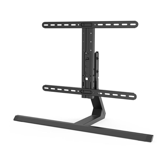
- Page 1 220869 TV STAND G Operating Instructions...
-
Page 2: Table Of Contents
Contents 1. Explanation of warning symbols and notes ......3 2. Package contents ..........4 3. -
Page 3: Explanation Of Warning Symbols And Notes
G Operating Instructions Thank you for choosing a Hama product. Take your time and read the following instructions and information completely. Please keep these instructions in a safe place for future reference. If you sell the device, pass on the illustrated quick start guide and the safety instructions in printed form to the new owner. -
Page 4: Package Contents
2. Package contents • TV bracket • Mounting kit • Safety instructions, illustrated quick start guide Mounting kit Ø7x35 (x4) M8x12 (x4) 5x38 (x4) M8x20 (x4) (x2) M8x30 (x4) (x2) M8x50 (x4) (x1) (x3) (x2) (x4) M6/M8 (x4) (x10) M8x10 (x4) 2x2 (x1) M8x20 (x4) 4x4 (x1) -
Page 5: Safety Instructions
4. Safety instructions Warning • Given the multitude of terminal devices and wall structures available on the market, the supplied mounting kit is unable to cover every option. • It occasionally happens that the screws for attaching the device to the bracket are too long. •... -
Page 6: Preparation And Assembly
6. Preparation and assembly Note • Never install the bracket alone. Seek assistance and help! • Different end devices have different connections for cabling and other devices. Before commencing the installation, check whether the necessary connections can still be reached after mounting. •... -
Page 7: Assembly Preparation
6.1 Assembly preparation 6.1.1 Attaching the covers to the strut • Attach the covers [F1] to the sides of the strut [G6] as shown above. 6.1.2 Mounting the strut on the stand • Connect the strut [G6] and the stand [G2] using the screws [E1]. Use the Allen key [E5] to do this. -
Page 8: Mounting The Support Leg On The Stand
6.1.3 Mounting the support leg on the stand Remove the cover [G7] from the support leg [G1] so that the screws can be fitted. Fit the support leg to the bracket using the screws [E2] as shown above. Use the Allen key [E5] for this. -
Page 9: Assembling The Vesa Plate
6.2 Assembling the VESA plate For 165 cm screen diagonal (65")* Mount the VESA arms [G5] either on the strut [G3] or on the adapter plate [G4] using the screws [E3] and the enclosed Allen key [E5], depending on the TV size. * Please note that the adapter plate [G4] must be attached to the strut [G3] for televisions with a screen diagonal of 65 inches. -
Page 10: Mounting On The Tv Set
6.3 Mounting on the TV set Note • Given the multitude of terminal devices structures available on the market, we cannot describe all possible mounting options here. • Please ensure that the bracket lays flat and evenly on the back of the television. •... -
Page 11: Mount The Vesa Arms On The Back Of The Tv Set
6.3.1 Mount the VESA arms on the back of the TV set C1, C2, D1, D2, D3, D4, B2, B3 Flat TV back Curved TV back C1, D1, D4 C2, D2, D4 D3, D4 M8x50 Ø 8x5 M8x45 (D4) • Mount the VESA arms the back of your TV set. •... -
Page 12: Mounting The Tv On The Tv Stand
6.4 Mounting the TV on the TV stand Get support and help from other people for the following assembly step. • Hang the TV with the mounted VESA plate on the wall bracket at the desired height. • Fix the TV to the stand using the screws [E3] as shown above. Use the Allen key [E5] for this. 7. -
Page 13: Secure Tv With Fastening Rope
8. Secure TV with fastening rope From a screen diagonal of 55 inches and an overall height* of more than 100 cm, the bracket must also be secured to the wall. max. 100 cm * measured from the lower edge of the base to the upper edge of the screen max. - Page 14 Step II 7 mm First use the mounting pieces [A3] as a template and measure if necessary to ensure that the position is correct. Please note that the height from the mounting piece to the stand must be 40 cm and the distance between the two mounting pieces 40-60 cm.
-
Page 15: Adjustment & Maintenance
9. Adjustment & maintenance Note Never adjust the bracket alone. Seek assistance and help! Note - tiltable / full-motion brackets • Ensure that no electrical cables are crushed or damaged during installation or adjustment. • During adjustment, ensure that the product is loaded symmetrically and that the maximum permitted carrying capacity is not exceeded. -
Page 16: Technical Data
11. Technical data Maximum load: 40 kg Screen diagonal: 81.0 - 165.0 cm (US: 32" - 65") Width/height/depth: 90.5 cm/ 83.0 cm/ 34.2 cm Swivel range: up to 70° (depending on device) Tilt range: -10°/+5° Compliant with VESA standard: 200 x 200 300 x 200 300 x 300 Mount:... -
Page 17: Warranty Disclaimer
In the event of a warranty claim, please contact us at Hama GmbH & Co KG, Dresdner Str. 9, 86653 Monheim, Germany, enclosing proof of purchase. You are also welcome to contact us at www.hama.de or by phone on...
Need help?
Do you have a question about the 00 220869 and is the answer not in the manual?
Questions and answers