
Related Manuals for Metro Therm Delta


Summary of Contents for Metro Therm Delta
- Page 1 Installation manual METRO Delta Liquid/water heat pump EXPERTS IN HEATING AND HOT WATER...
- Page 2 We reserve the right for printing errors.
-
Page 3: Table Of Contents
Heating curve ......30 Cooling curve ......31 Chapter METRO DELTA... -
Page 4: Important Information
If the refrigerant circuit is breached /opened whilst the compressor is running, air can enter the process of METRO THERM. Rights to make circuit. This can cause unusually high pressure in the any design or technical modifica- process circuit, which can cause bursts and personal tions are reserved. - Page 5 That there is continuity of earth bonding. • hand. Have a dry powder or CO2 fire extinguisher adjacent to the charging area. Chapter Important information METRO DELTA...
- Page 6 Equipment such as inverters, standby sets, medical high frequency equipment and telecommunications equipment can affect the unit and cause malfunc- tions and breakdowns. The unit can also affect Chapter Important information METRO DELTA METRO DELTA...
-
Page 7: Product Certifications
Improper disposal of the product by the user results in administrative penalties in accordance with cur- rent legislation. Chapter Important information METRO DELTA... -
Page 8: Inspection Of The Installation
Outdoor sensor (if required) Room sensor (if required) Thermostat (if required) Safety breaker / fuse Earth circuit-breaker Installer information Company name: Pipe installation Installer name: Contact information: Company name: Electric installation Installer name: Contact information: Chapter Important information METRO DELTA METRO DELTA... -
Page 9: Check List Before Commissioning
Is the heat pump on, and the mode set to AUTO? Operating the heat pump Does the heat pump make any unexpected noise? * Take care to protect the heat pump against freezing - see "4. Installation of the unit" on page 18 Chapter Important information METRO DELTA... -
Page 10: Delivery And Handling
The top of the packaged unit contains the When unpacking, let the unit remain on the accessories and the drainage hoses for reinforced cardboard frame to prevent venting the unit when commissioning. damage to the pipes underneath the unit. Chapter Delivery and handling METRO DELTA METRO DELTA... - Page 11 Units Sheet Size THIS DOCUMENT IS THE PROPERTY OF METRO THERM A/S. IT SHALL NOT -NEITHER INITS ORIGINAL NOR IN ANY MODIFIED FORM, IN WHOLE NOR IN PART- BE REPRODUCED,DISCLOSED TO A THIRD PARTY, OR USED FOR ANY Step 2 - Install the bracket on the wall with respect PURPOSE OTHER THAN THAT FORWHICH IT IS SUPPLIED, WITHOUT THE WRITTEN CONSENT OF METRO THERM A/S.
-
Page 12: Assembly
• The drain hoses for venting the unit’s primary and secoundary systems are placed in the top tray of the packaged unit as an accessory. • Beware of the PI Diagram and connections placement shown on page 16 and 17. Chapter Delivery and handling METRO DELTA METRO DELTA... -
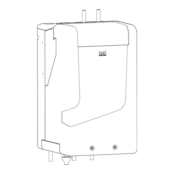
Page 13: Heat Pump Design And Dimensions
3. HEAT PUMP DESIGN AND DIMENSIONS Dimensions BOTTOM VIEW RIGHT SIDE VIEW FRONT VIEW LEFT SIDE VIEW Chapter Heat pump design and dimensions METRO DELTA... -
Page 14: Mechanical Design Of The Unit
Mechanical design of the unit QN12 QN13 XL11 QN11 QN10 Chapter Heat pump design and dimensions METRO DELTA METRO DELTA... - Page 15 Heating circulation pump, The high temperature limiter thermostat for the back-up heater is placed by the electrical panel in the modulating top cabinet of the unit. EB1: Electrical back-up heater, 1.5 kW Chapter Heat pump design and dimensions METRO DELTA...
-
Page 16: Pi Diagram
OFF = A ON = B Active cooling version XL21 XL20 XL4b XL13a QN12 XL3a QN13 XL3b XL12 XL4a XL13b Passive cooling/heating XL11 QN11 QN10 BT AUX1 XL10 XL14 XL15 Chapter Heat pump design and dimensions METRO DELTA METRO DELTA... -
Page 17: Pipe Connection
81 mm 40 mm BOTTOM VIEW 100 mm 100 mm 100 mm 100 mm 100 mm 100 mm 100 mm 74,5 mm 74,5 mm 74,5 mm 74,5 mm 74,5 mm 74,5 mm Chapter Heat pump design and dimensions METRO DELTA... -
Page 18: Installation Of The Unit
50 °C the heat exchangers. Table 1. The temperature limit for the primary inlet. *During cooling the compressor can work until the brine circuit reaches 70 °C. Chapter Installation of the unit METRO DELTA METRO DELTA... -
Page 19: The Secondary System
It is recommended that all heat pumps have access to at least 10 liters of volume per effective kW they produce. A heat pump capable of producing 5 kW should therefore have access Chapter Installation of the unit METRO DELTA... - Page 20 BT AUX2/BT AUX3 Shut-off valve Filling valve RECOMMENDED INSTALLATION OPTION B Ground source List of components Filter strainer Safety valve Expansion tank Non-return valve BT AUX2/BT AUX3 Shut-off valve Filling valve Chapter Installation of the unit METRO DELTA METRO DELTA...
-
Page 21: Electrical Design
Units Sheet Size THIS DOCUMENT IS THE PROPERTY OF METRO THERM A/S. IT SHALL NOT -NEITHER INITS ORIGINAL NOR IN ANY MODIFIED FORM, IN WHOLE NOR IN PART- BE REPRODUCED,DISCLOSED TO A THIRD PARTY, OR USED FOR ANY PURPOSE OTHER THAN THAT FORWHICH IT IS SUPPLIED, WITHOUT THE WRITTEN CONSENT OF METRO THERM A/S. -
Page 22: Communication Connection
0-10V lowest rows of pins. So the 2 top rows are left un- used. ODBUS SLAVE If there is trouble when connecting to the bluetooth, check whether the print is 24VDC installed correctly. Chapter Electrical design METRO DELTA METRO DELTA... -
Page 23: Connection Between Products
For example, place the sensor outdoor if and removed afterwards for further use at the control strategy is degree minutes and different units. to adjust through the heating curve. Chapter Electrical design METRO DELTA... - Page 24 L20 to ANA as shown on the picture. SMART GRID - SG Connect the SG signal as shown below. Move the two jumper pins JP1 and JP2 to the posi- tion of DIG as shown on the picture. Chapter Electrical design METRO DELTA METRO DELTA...
-
Page 25: Electrical Connection-Diagram And Electri
Electrical connection-diagram and electrical box Chapter Electrical design METRO DELTA... -
Page 26: Commissioning And Adjusting
Pressure Rating, secondary system ACCESS TO THE FILLING PORTS Step 1 - Remove the screws from front panel. THE PRIMARY SYSTEM Step 1 - Connect the filling hose to the filling port XL2. XL11 Chapter Commissioning and adjusting METRO DELTA METRO DELTA... - Page 27 5.4.3.5 of return hose from the filling station. the controls for the unit. Adjust the time ON and OFF for the cirkula- tion pump, GP1, in menu 5.4.3.6 and menu 5.4.3.7. Chapter Commissioning and adjusting METRO DELTA...
-
Page 28: Unit Start Up
4. Go to menu 5.4.7.2 restore setings to unit. 5. Restore the settings on the new unit. The new unit is now set up with the ex- act same settings as the one previously installed. XL11 Water Chapter Commissioning and adjusting METRO DELTA METRO DELTA... -
Page 29: Prevent Freezing
When the temperature in the room reaches the set hysteresis, the unit will stop the heating/cooling production. Adjust the min. / max. supply temperature for the secondary side (menu 5.1.4.) according to whether there is installed radiators or underfloor heating. Chapter Commissioning and adjusting METRO DELTA... -
Page 30: Heating Curve
Supply temperature Supply temperature (°C) Curve slope (°C) Adjusted slope (°C) (°C) Supply t Supply temperature Framledningstempereratur (°C) (°C) Max. Outdoor temperature erature Outdoor temperature (°C) peratur Utetemperatur (°C) (°C) (°C) Min. Chapter Commissioning and adjusting METRO DELTA METRO DELTA... -
Page 31: Cooling Curve
The cooling curve is adjusted just as the heating curve with a slope and a offset depending on the outdoor temperature. Supply temperature Supply temperature (°C) (°C) Outdoor temperature Outdoor temperature erature Adjusted slope peratur (°C) (°C) (°C) Chapter Commissioning and adjusting METRO DELTA... -
Page 32: Decommissioning Of The Refrigerent
Before attempting the procedure, ensure that: 1. Mechanical handling equipment is available; 2. All personal protective equipment is available and being used correctly; 3. The recovery process is supervised at all times by a competent person; Chapter Commissioning and adjusting METRO DELTA METRO DELTA... -
Page 33: Operational Status
Time 3 occurred. Check the troubleshooting table in section "Troubleshooting - Error codes" on page 62 Time 4 Time 5 Table 7. View of the sequence for the combined state. Chapter Operational status METRO DELTA... - Page 34 Table 12. The sequencing when the the unit is operating in the heating element turns on. pause state. If the temperature for the primary system, BT1, is below -15 °C the backup state will activate. Chapter Operational status METRO DELTA METRO DELTA...
-
Page 35: Device Control Introduction
This menu will lock the screen for 5 sec. to safely Settings for time, date, language and display. Infor- clean it. mation regarding this menu can be found at "Menu 4 - My system" on page 43 Chapter Device control introduction METRO DELTA... -
Page 36: Software Update
Note that the display will flash and go black while the software update is taking place. This is normal. Chapter Device control introduction METRO DELTA METRO DELTA... -
Page 37: Control Menu
08.23 Tuesday Tuesday E-59 HiT_SinkExtErr3xWeek_SH E-59 HiT_SinkExtErr3xWeek_SH 06.12.22 12.05 06.12.22 12.05 E-58 HiT_SinkExtErr_SH E-58 HiT_SinkExtErr_SH 06.12.22 12.03 06.12.22 12.03 E-58 HiT_SinkExtErr_SH E-58 HiT_SinkExtErr_SH 04.12.22 13.47 04.12.22 13.47 E-58 HiT_SinkExtErr_SH E-58 HiT_SinkExtErr_SH 03.12.22 14.01 03.12.22 14.01 Chapter Control Menu METRO DELTA... - Page 38 Press to conform the chosen setting. TEMPERATURE SETTING (WITH COOLING CURVE) When using degree minutes for the climate control, and an additional sensor (AUX 3) is installed indoor, Chapter Control Menu METRO DELTA METRO DELTA Current menu Date Time...
- Page 39 To set up the custom curve, input the supply temperatures corresponding to different outdoor temperatures for the Curve slope. The curve offset is adjusted by increasing or decreasing the same amond for the supply tempera- Chapter Control Menu METRO DELTA...
-
Page 40: Menu 2 - Hot Water
ECO mode temperature is set to under 50 Select the legionella temperature setpoint for the °C. hot water tank. Press the temperature value for 2.3.2. Legionella temperature setpoint and use the Chapter Control Menu METRO DELTA METRO DELTA... - Page 41 At a water temperature of 70 °C, all le- gionella bacterier dies at ones. CAUTION It is recomended to run the legionella pre- vention program ones a week. Choose which weekday through 2.3.3. Legionella day Chapter Control Menu METRO DELTA...
-
Page 42: Menu 3 - Info
The information can not be adjusted in this menu. If the unit encountered a problem which needs the unit to be manual reset. Then restart the unit. The unit can at any point be reset. Chapter Control Menu METRO DELTA METRO DELTA... -
Page 43: Menu 4 - My System
• SG1 = Closed, SG2 = Open (SG), the photovoltaic function (PV) or by neither. All operation is turned Off. - This could be in case of high electical prices. • SG1 = Open, SG2 = Closed. Chapter Control Menu METRO DELTA... - Page 44 • The hot water setpoint is changed to the legionella setpoint value. If the target tem- perature in the tank are met. Then the next legionella cycle will be cancelled. Chapter Control Menu METRO DELTA METRO DELTA...
-
Page 45: Menu 5 - Service
Deactivated : Passive cooling, Combined cooling and Ac- garding degree minutes in connection to the outdoor tive cooling. temperature. Select which operational modes the unit should run in. Read "7. Operational status" on page 33 for further information. Chapter Control Menu METRO DELTA... - Page 46 Equily if the outdoor temperature is below 25 °C the average indoor temperature over a periode to help unit reset the counter to 0 and the compressor stops stabilize the production of the heating/cooling. production of cooling. Chapter Control Menu METRO DELTA METRO DELTA...
- Page 47 Secondary side, low temp. pause hysteresis - Menu somewhere with increased risk of conden- 5.1.4.4 sation. Setting range: 0,5 to 5 °C Factory setting: 2 °C This menu applies to the unit, no matter the control strategy chosen. Chapter Control Menu METRO DELTA...
- Page 48 AUX1 detect a temperature of 15 °C + 2 °C. Choose which space heating type to use in the instal- lation, as this will indicate the currect Delta T. MENU 5.1.30.1 - SENSOR SETTING (BT Underfloor heating systems demands lower supply...
-
Page 49: Menu 5.2 Hot Water
In Boost mode the heatpump runs with both com- pressor and heating element turned on, to reach the set temperature faster. The compressor and heating element stops automatically when the sensor BT3, registere a higher temperature then the setpoint. Chapter Control Menu METRO DELTA... -
Page 50: Menu 5.3 Info
MENU 5.3.3 - PUMP Here is shown information regarding the operational status and statistics of the pumps on the primary and secondary side of the system. The information can not be adjusted in this menu. Chapter Control Menu METRO DELTA METRO DELTA... -
Page 51: Menu 5.4 My System
Primary side, max. temperature - Menu 5.4.1.2 Tarif, and slave unit operations. Setting range: 20 to 80 °C PUMP SETTINGS to adjust the pumps speed, Delta T Factory setting: 70 °C and activation of the flushing program. Primary side, min. temperature in passive state - Menu 5.4.1.3... - Page 52 10, and the unit will run in passive state. If the Delta T is calculated to be under the set point PRIMARY SIDE, MIN. AND MAX TEMPERATURE (5 °C) in menu 5.4.1.4 then the combined stat starts These setpoints are a safety measure to ensure to run.
- Page 53 ADDITIONAL RELAY - MENU 5.4.2.1 Here you can connect to the addtional relay for a smartrix termostat or to active cooling. Go to "5. Electrical design" on page 21 to find how to connect to the relay. Chapter Control Menu METRO DELTA...
- Page 54 MENU 5.4.6 - DISPLAY BACKUP SAVE SETTINGS TO DISPLAY When commisioning is done save the settings to a backup in the display. Removal of the display will not affect the operation of the unit. Chapter Control Menu METRO DELTA METRO DELTA...
-
Page 55: Service
21 for location and information on the specific cabels. Step 2.A - Connect a pipe or tube to the filling ports XL11 and XL2, place the open end of the tube to- wards a drain or bucket. XL11 Chapter Service METRO DELTA... - Page 56 If the fault cannot be corrected immedi- ately but it is necessary to continue operation, an adequate temporary solution shall be used. This shall Chapter Service METRO DELTA METRO DELTA...
-
Page 57: The Primary System
There is a risk of burns. When refilling the system, use the filling port XL2 again. Remember to vent the system for air through QN7 and QN8, before starting the system up again. Chapter Service METRO DELTA... -
Page 58: The Secondary System
Safety valves must be checked periodically to ensure full function. Follow the instruction delivered with the hot water tank. Step 3.b - Now remove the bottom by carefully drag- ging the element toward you. Chapter Service METRO DELTA METRO DELTA... -
Page 59: Operational Disruption
• Sudden ultra short (<500 ms) power outage, can under certain conditions cause the compressor to blow the 8A fuse on the electical board when the unit starts up again. Chapter Operational disruption METRO DELTA... - Page 60 1.30.1.1 and 1.30.1.2 the same porary solution could be to change the setting amount. in menu 2.1.1 to boost, this will increase the = Air in the system temperature and therefor the amount of hot Chapter Operational disruption METRO DELTA METRO DELTA...
- Page 61 = Minimum time between compressor starts are not achieved yet. = Wait at least 30 min. and control thereafter if the compressor have started. = Alarm triggered = Follow the instructions in the table below. Chapter Operational disruption METRO DELTA...
-
Page 62: Troubleshooting - Error Codes
Temperature (BT2) too high in the primary system. The unit automatically shut down all production Possible cause is descriped under error code E-26 for 10 min. and restarts afterwards. Possible solution is descriped under error code E-26 Chapter Operational disruption METRO DELTA METRO DELTA... - Page 63 If the error persist after a thorough venting, then the cause is with the software or compressor module. = Update the software and reset the alarm. = Does that not work. Then the compressor module needs to be inspected by the manufacturer. Chapter Operational disruption METRO DELTA...
- Page 64 Possible cause: = Check whether the temperature sensors are cor- = Control software is damaged. rectly placed and are reading properly. = Operational limit set wrong at the factory. = Update the software. Chapter Operational disruption METRO DELTA METRO DELTA...
- Page 65 = In case of the secondary system being warmer is 50 °C. then the primary system. - The eg. boiler will eventually cold down. = Reset the alarm and check the operation of the unit for 15 min. Chapter Operational disruption METRO DELTA...
- Page 66 The reaction and alarm ensure that there is heating/cooling capacity when the compressor is This error is always cause by disturbance in the running. electrical operation of the compressor. Possible cause is discriped under error E-43. Chapter Operational disruption METRO DELTA METRO DELTA...
- Page 67 10 min. and restarts afterwards. The maximum condenser temperature (BT7 for Check under error code E-45 for possible solu- heating, BT2 for cooling) is 75 °C. tions. Check error code E-45 for possible cause. Chapter Operational disruption METRO DELTA...
- Page 68 10 min. and restarts afterwards. After 5 minutes with the compressor turned on, and no temperature (BT6) increase from the com- pressor indicates the compressor is blocked. Possible cause is descriped under error code E-51. Chapter Operational disruption METRO DELTA METRO DELTA...
- Page 69 = Ensure the coil is properly vented. - Revent if reading. necessary. = Ensure the boiler sensor is properly placed in the right immersion tube. = Reset the alarm and observe the operation of the unit. Chapter Operational disruption METRO DELTA...
- Page 70 = Check under E-55 if the error is cause by too low = Check under E-55 if the error is cause by too low a temperature. a temperature. Chapter Operational disruption METRO DELTA METRO DELTA...
- Page 71 Possible cause is descriped under error code E-59. The reaction and alarm prevents the temperature in the underfloor heating circuits or radiators from getting too high. Possible solution is descriped under error code E-59. Chapter Operational disruption METRO DELTA...
- Page 72 BT4, BT5 and BT AUX1 reach Possible solution is descriped under error code above the setpoint set by the installer (menu E-62 5.1.4) Possible cause is descriped under error code E-62 Chapter Operational disruption METRO DELTA METRO DELTA...
- Page 73 = Does that not work. Then the compressor module needs to be inspected by the manufacturer. *Note; does the error occur during the cooling operation. Then the problem area is in the primary system, not the secondary system. Chapter Operational disruption METRO DELTA...
-
Page 74: Accessories
12. ACCESSORIES Temperature sensor OUTSIDE/INDOOR TEMP. SENSOR METRO THERM No.: 8153324999 Intented for connection to the BT AUX3. Bluetooth module BLUETOOTH PRINT METRO THERM No.: 8153330999 CONFIG APP Available in App store or Google Play. App includes illustration of heating curve and startup guide for easy commisioning and adjustment of the unit. -
Page 75: Technical Data
Maximum volume of mixed water at 40 °C, V 291.9 Heating performance data according to EN14511 B0/W35 W10/W35 W10/W55 B5/W35 B0/W55 Heating Capacity [kW] Performance data for cooling according to EN14511 W35/W18 W25/W15 Heating Capacity [kW] Chapter Technical data METRO DELTA... - Page 76 Min. recomended heat source flow l/min Heat source connections Ø22 Secondary system requirements Pressure Rating Max/min. operating temperature °C 70/25 Water connection Ø22 Refrigerant requirements Refrigerant type R290 Refrigerant Charge Max pressure in circuit Chapter Accessories METRO DELTA METRO DELTA...
-
Page 77: Workarea
This ensures the need for heating is always covered. Contract the supplier of the components for the primary system in case of doubt regarding the dimensioning. Primary side, return temperature °C Sink side capacity: Chapter Accessories METRO DELTA... -
Page 78: Available Pressure
PRESSURE DROP WITH IPA (30%) CONCENTRATION This graph depicts the pressure drop through the pri- mary system. (incl. pumpe, pipes and heat exchanger) Pressure difference [kPa] Volume flow rate [l/h] with Ethylene glycol oncentration) Volume flow rate [l/h] Chapter Accessories METRO DELTA METRO DELTA... - Page 79 Chapter Accessories METRO DELTA...
-
Page 80: Energy Label
14. ENERGY LABEL Supplier's name: METRO THERM A/S METRO Delta P Model: Triple Solar PVT heat pump Temperature application °C Declared load profile for water heating Seasonal space heating energy A+++ A+++ efficiency class, average climate: Water heating energy efficiency... - Page 81 Water heating energy efficiency ƞ Daily electricity consumption 3,500 Daily fuel consumption elec fuel Annual electricity consumption Annual fuel consumption Approved by: Contact details METRO THERM A/S - Rundinsvej 55 - 3200 Helsinge - Denmark Chapter Energy label METRO DELTA...
- Page 82 Water heating energy efficiency Daily electricity consumption 3,500 Daily fuel consumption elec fuel Annual electricity consumption Annual fuel consumption Approved by: Contact details METRO THERM A/S - Rundinsvej 55 - 3200 Helsinge - Denmark Chapter Energy label METRO DELTA METRO DELTA...
-
Page 83: Index
Decommissioning of the refrigerent 32 Decommissioning process 32 Language 43 Degree minutes 46, 50 LED Indicator 33 Delta T in passive state - menu 5.4.1.4 52 Legionella 34, 40 Dimensions 13 List of components 15 Display 23, 35 Low room temperature 60... - Page 84 Time and date 43 Pump speed 53 Transport 10 PV 24, 31, 43 Troubleshooting 59, 62 Recommended Installations 20 Recovery 7 Removal and evacuation 57 Reset 54, 59 Restore first time reset 54 Restore from backup 54 Chapter Index METRO DELTA METRO DELTA...
- Page 85 Chapter Index METRO DELTA...
- Page 86 Chapter Index METRO DELTA METRO DELTA...
- Page 87 Chapter Index METRO DELTA...
- Page 88 MET RO T HER M A/ S ME TRO THERM A / S RUNDINSVE J 5 5 RUNDINSVEJ 55 DK3 200 HELS IN GE DK32 00 HE LSI NG E INFO@ME TRO TH ER M. DK INF O@METROT HE RM. D K WWW.MET R OTH ER M.
Need help?
Do you have a question about the Delta and is the answer not in the manual?
Questions and answers