
Related Manuals for Metro Therm SHK 20-200


Summary of Contents for Metro Therm SHK 20-200
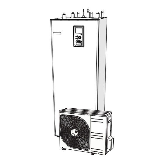
- Page 1 Installation and operating manual SHK 20-200 Indoor unit Cooperating with air heat pumps EKSPERTER I VARME OG VARMT VAND 11-12-2023 31573...
-
Page 3: Table Of Contents
3 Design of the indoor unit ___ 16 Menu 1 - INDOOR CLIMATE ________ 48 Menu 2 - HOT WATER ___________ 49 SHK 20-200 _________________ 16 Menu 3 - INFO ________________ 49 Menu 4 - MY SYSTEM ___________ 50 4 Pipe connections ________ 18... -
Page 4: Important Information
The serial number is located at This symbol indicates danger the bottom of the rating plate, on to the appliance or person. the top cover SHK 20-200 and consists of 14 digits. This symbol indicates tips Serial number that will make it easier to SHK (PF1) operate the product. - Page 5 Electric power supply Connecting communication Perimeter protection Protection, indoor unit Building protection Outdoor temperature sensor Room sensor Current sensor Safety circuit breaker Residual-current device Setting the thermostat to emergency mode Miscellaneous Docked to SHK 20-200 Section 1 | Important information...
-
Page 6: Metroair L - Safety Information
Must not be punctured or burned. Be aware that the refrigerant leakage. may be odourless. NOTE Work on refrigerant systems must be carried out by per- sonnel who have knowledge and experience of working with flammable refrigerants. Section 1 | Important information SHK 20-200... - Page 7 The plosions. area surrounding the worksite must be cordoned off. Ensure that the area is made safe by removing combus- tible material. SHK 20-200 Section 1 | Important information...
- Page 8 • The actual filling quantity is ap- owner, so that all parties have been propriate for the magnitude of informed. the space where the parts con- taining refrigerant are installed. • Ventilation equipment and outlet SHK 20-200...
- Page 9 (the leak tracing SHK 20-200...
- Page 10 • Ensure that the cooling system The system must be emptied in ac- is grounded before the system is cordance with the section “Remov- filled with refrigerant. al and draining”. Section 1 | Important information SHK 20-200...
- Page 11 – not even temporarily. 10. When the containers have been filled correctly and the process is complete, close all shut-off valves in the equipment and remove and containers and equipment from the installation immediately. SHK 20-200 Section 1 | Important information...
- Page 12 Only electrical heating and, if possible, chilled before col- of the compressor housing may be lection. used to quicken draining. Drain oil from the system in a safe manner. The collection equipment must Section 1 | Important information SHK 20-200...
- Page 13 Maintenance and repair that re- quires the skill of another person must be carried out under the su- pervision of someone with the above expertise. SHK 20-200 Section 1 | Important information...
-
Page 14: Delivery And Handling
5,66 - Total refrigerant amount SHK 20-200/6 with the L6.1 unit is filled with 1.3 kg of re- - H = installation height to bottom edge of AGS 10 and ventila- frigerant from the factory and therefore has no specific re- tion holes SHK 20-200. -
Page 15: Installation Location
Instalation and user manual indoor unit, however the recommended distance is 150 • Reduction 3/8” on 1/4” (SHK 20-200/12 ) mm. All servicing of SHK 20-200 can be carried out from the front. 70-150mm Outdoor temperature Safety group with safe- sensor (1 pc.) -
Page 16: Design Of The Indoor Unit
3 Design of the indoor unit SHK 20-200 XL11 XL10 XL53 XL52 AA23 BT30 K1A-K3A AA2:X15 AA2:X4 BT64 GP12 QN12 BT12 BT15 BT25 BT63 BT71 QN10 Section 3 | Design of the indoor unit SHK 20-200... - Page 17 Hot water tank BT25 Temp. sensor, heating medium supply BT63 Temp. sensor, supply heating medium behind immersion heater BT64 Temp. sensor, cooling operation system supply BT71 Temp. sensor, heating medium return SHK 20-200 Section 3 | Design of the indoor unit...
-
Page 18: Pipe Connections
4 Pipe connections The SHK 20-200 unit is not equipped with a shut-off valve General information for the climate system. In order to facilitate future servic- ing, the shut-off valves should be installed on the outside Pipe installation must be carried out in accordance with the of the indoor unit. -
Page 19: System Diagram
(H) between the vessel and the highest- posi- The SHK 20-200 indoor unit is equipped with a storage tank tioned radiator, see drawing. An with a hot water coil, expansion vessel, safety group, elec- initial pressure of 0.5 bar (5 mvp) - Page 20 HS1 -BP4 -BT7 -GP11 -BT1 -EB101 SHK 20-200 -BT6 The diagram above is a basic 2-pipe diagram with a buffer. tem components, i.e. GP12, extension modules (additional If a buffer is used in the installation, remember to transfer heating/cooling circuits), etc. The 2-pipe system can be se- the BT25 sensor to the installation in accordance with the lected in the SERVICE section, menu 5.2.4.
- Page 21 HS1 -BP4 -BT7 -GP11 -BT1 -EB101 SHK 20-200 -BT6 If a buffer is used in the installation, remember to transfer controller supports all system components, i.e. GP12, ex- the BT25 sensor to the installation in accordance with the tension modules (additional heating/cooling circuits), etc.
- Page 22 15kW. Recommended order of assembly • It is recommended that you install the SHK 20-200 unit in a room which is equipped with a floor drain and pro- Dock the SHK 20-200 unit to the central heating sys- tected against freezing.
-
Page 23: Pipe Connections
Connection 1/2” (SHK 20-200/6) Connection 5/8” (SHK 20-200/12) XL18 XL53 Liquid cooling medium Connection 1/4” (SHK 20-200/6) Connection 3/8” (SHK 20-200/12) - 1/4” adapter for L10.1 units included. XL18 Connection, return to an additional heat source Ø22 mm XL19 XL19 Connection, supply from additional heat source Ø22 mm 103 mm... -
Page 24: Docking The Indoor Unit
Condensate elimination Docking the indoor unit The SHK 20-200 unit has a condensate hose to drain the condensation water from the drip tray located under the hot water tank. The pipe drains all of the condensation wa- Docking the climate system ter away from the appliance, minimizing the risk of damage. - Page 25 Refrigerant connection pipeline specification Caution L6.1 The SHK 20-200/12 unit is equipped with a 3/8” to 1/4” liquid connection adapter (XL53). The Gas pipe (Ø ext.) Liquid line (Ø ext.) adapter should be used when the control panel is connected to the L10.1 Split outdoor unit.
- Page 26 (QM35, QM36) closed. In order to fill the pipes of SHK 20-200 with refrigerant, they must be reopened. Pressure test and leak test Both SHK 20-200 and METROAIR L are factory tested for Insulating refrigerant pipes pressure and leakage, but the refrigeration pipe connec- tions between appliances should be checked for leakage •...
- Page 27 INSTALLATION REQUIREMENTS Indoor unit SHK SHK 20-200/6 SHK 20-200/12 Compatible outdoor module L6.1 L10.1 Requirements Max pressure, climate system 0,3 MPa (3 Bar) Highest recommended supply / return temperature at di- +55/+45°C mensioned outdoor temperature Max. temperature in the unit SHK +70°C...
-
Page 28: Connection Options
During heat- The SHK 20-200 unit is not equipped with a shut-off valve ing of the water in the tank, the pressure increases, which... - Page 29 The hydraulic system should be suitable for he- ating and cooling and have appropriate thermal insulation (allowed for cooling). Additional accessories and the connection options and methods for these are described in the instructions for AXC 30 and ECS 41. SHK 20-200 Section 4 | Pipe connections...
-
Page 30: Dhw Circulation
XL5 plug. of the tank. Install the circulation pump on the pipe outlet of the SHK 20-200 device, and then connect its control to the controller or AA5 card. Install the control box and the front panel. -
Page 31: Metroair L Outdoor Unit
„heavy side” and two people are re- For details on installing the outdoor unit, refer to the install- quired to get the METROAIR L up. er manual of the outdoor unit. SHK 20-200 Section 5 | METROAIR L outdoor unit... -
Page 32: Lift From The Pallet To Final Positioning
• The insulation must be tightly fitted to the bottom of the condensation water trough. The outlet of the condensation water drainage pipe must be at a depth that is frost-free. Section 5 | METROAIR L outdoor unit SHK 20-200... -
Page 33: Maintenance Of Metroair L
• The installation length can be adjusted by the size of the siphon. Caution If none of the recommended options will be used, proper drainage of condensate must be ensured. SHK 20-200 Section 5 | METROAIR L outdoor unit... -
Page 34: Dimensions
Dimensions L6.1 40º 40º L10.1 30º 30º W i dok z góry Section 5 | METROAIR L outdoor unit SHK 20-200... -
Page 35: Installation Location
Max. sound value, silent 49,0 43,0 39,5 37,0 35,0 33,5 32,1 31,0 29,9 29,0 mode 60 Hz 1 Sound power level, LW(A), according to EN12102 2 Sound pressure calculated according to directivity factor Q=4 SHK 20-200 Section 5 | METROAIR L outdoor unit... -
Page 36: Electrical Connections
• Use the UB1 cable grommet (as marked in the illustra- tion) to lead the cables to the SHK 20-200. In the UB1 AA27 grommet, the cables are routed through the entire in- door unit from the rear wall towards the front. -
Page 37: Connections
Remove the bridge to use dual- -tariff control. NOTE If a 400V connection is used, the maximum po- wer of the electric additional heater placed in the SHK 20-200 unit is 9 kW. SHK 20-200 Section 6 | Electrical connections... - Page 38 The automatic heating control system, the circulation company, it is recommended to connect the neu- pump and their wiring in SHK 20-200 are internally protect- tral wire from the power circuit (meter). ed by miniature circuit breaker C10 (FA1). The METROAIR L outdoor unit and accessories are internally protected in Power supply connection 230 V...
-
Page 39: Additional Connections
Connecting the outdoor temperature sensor terminal block (X10) in SHK 20-200 . The outdoor temperature sensor BT1 (included) should be connected to the SHK 20-200 unit via terminal block NOTE AA3-X6:1 and AA3-X6:2. Wiring must be secured so that the terminal block... -
Page 40: Settings
35-45°C to maintain comfort in the room and efficient operation of the system. Rozdzielnia Electrical elektryczna distribution unit BA-SVM 10-200 SHK 20-200 -T1 -T2 -T3 NOTE 1 2 3 4 The maximum available heater power in emer- AA3-X4 AA3-X4 gency mode is 3kW. -
Page 41: Commissioning And Adjusting
7 Commissioning and adjusting Preparations Filling the DHW heater at SHK 20-200 Check that the switch for the control module is in po- sition „ ”. Open the hot water tap in the building to the tank. Check whether the drain valve has been completely Open the valve cutting off cold water. -
Page 42: Circulation Pump
Commissioning NOTE Pump speed Commissioning of the system must be carried out The circulation pump in SHK 20-200 is controlled by fre- by a person with appropriate authorizations and quency, and is automatically regulated via control and manufacturer’s authorization! based on the heating / hot water demand. -
Page 43: Pressure Relief Valve
To view the help text: Use the knob to select the help symbol. Press the OK button. The help text often consists of several windows that you can scroll between using the knob. SHK 20-200 Section 7 | Commissioning and adjusting... -
Page 44: Control - Introduction
The knob can be turned to the right or left. You can: • scroll in menus and between options. • increase and decrease the values. • change page in multiple page instructions (for ex- ample help text and service info). Section 8 | Control - Introduction SHK 20-200... -
Page 45: Menu System
7 seconds, when you are in the start menu in heating is active. chapter MENU 5. Required additional equipment EME. This symbol indicates whether pool heating is active. Required additional equipment POOL This symbol indicates whether cooling is active. SHK 20-200 Section 8 | Control - Introduction... - Page 46 To select another option: Mark the applicable option. One of the options is pre-selected (white). Press the OK button to confirm the selected option. The selected option has a green tick. Section 8 | Control - Introduction SHK 20-200...
- Page 47 To change character table, press the Back button. If a menu only has one character set the keyboard is displayed directly. When you have finished writing, mark „OK” and press the OK button. SHK 20-200 Section 8 | Control - Introduction...
-
Page 48: Control
1.9.4 - room sensor settings 1.9.5 - cooling settings 1.9.6 - fan return time 1.9.7 - own curve 1.9.7.1 - heating 1.9.7.2 - cooling 1.9.8 - point offset The ERS additional equipment is necessary. Section 9 | Control SHK 20-200... -
Page 49: Menu 2 - Hot Water
Menu 3 - INFO 3 - INFO 3.1 - service info 3.2 - compressor info 3.3 - add. heat info 3.4 - alarm log 3.5 - indoor temp. log The AXC 30 additional equipment is necessary. SHK 20-200 Section 9 | Control... -
Page 50: Menu 4 - My System
4.9.1 - op. prioritisation 4.9.2 - auto mode setting 4.9.3 - degree minute setting 4.9.4 - factory setting user 4.9.5 - schedule blocking 4.9.6 - schedule silent mode The POOL 40 additional equipment is necessary. Section 9 | Control SHK 20-200... -
Page 51: Menu 5 - Service
The OPT additional equipment is necessary. The ECS additional equipment is necessary. The HTS 40 additional equipment is necessary. The SOLAR 42 additional equipment is necessary. The EMK 300 additional equipment is necessary. The MODBUS additional equipment is necessary. SHK 20-200 Section 9 | Control... -
Page 52: Start Guide
„ ? ”. Factory setting: presettings Factory setting: radiator Factory setting:-20.0 DOT C 5/17 Accessories In this menu it is possible to activate additional connected accessories. More information after selecting „ ? ”. Section 9 | Control SHK 20-200... - Page 53 + 55 for radiator heating. 13/17 Heating curve In this menu it is possible to edit the heating curve specified for the SHK 20-200 unit. More information after selecting „ ? ”. Factory setting: Heating curve: 7 9/17 Installed slaves In this menu, it is possible to select slave devices.
-
Page 54: Settings For The User
Reminder to complete the checklist in the first chapter of the user manual. 17/17 Start guide In this menu, we can decide whether the start guide will run again the next time the system is started. Section 9 | Control SHK 20-200... - Page 55 Use the control knob to set a new value. Confirm the new setting by pressing the OK button. This menu is intended for advanced users. This menu has Curve 0 is an own curve created in menu 1.9.7. several sub-menus. SHK 20-200 Section 9 | Control...
- Page 56 (min. supply temp.heating/cooling) set the unstable room temperature. minimum temperature on the supply temperature to the climate system. This means that SHK 20-200 never calcu- lates a temperature lower than that set here. Factory setting: inactive If there is more than one climate system the setting can be made separately for each system.
- Page 57 Menu 1.9.5 - cooling settings (if active) Menu 1.9.8 - point offset You can use SHK 20-200 to cool the house during hot peri- Make the correction for the heating curve at a certain out- door temperature here. ods of the year. More information after selecting „ ? ”.
- Page 58 - Lux mode gives the greatest possible amount of hot water. In this mode the immersion heater may be par- tially used to heat hot water, which may increase operating costs. Section 9 | Control SHK 20-200...
- Page 59 No changes can be made. The information is on several pages. Turn the con- trol knob to scroll between the pages. More information af- ter selecting „ ? ”. SHK 20-200 Section 9 | Control...
- Page 60 Menu 4.1.3 - internet To facilitate fault-finding the heat pump operating status at Here you make settings for connecting SHK 20-200 to the alarm alerts is stored here. You can see information for the internet. More information after selecting " ? ".
- Page 61 If you choose to switch off hot water production during the vacation “periodic increase” (preven- ting bacterial growth) are blocked during this time. „periodic increase” started in conjunction with the vacation setting being completed. SHK 20-200 Section 9 | Control...
- Page 62 400 DM diff. between additional steps: 30 DM Caution Higher value on „start compressor” gives more compressor starts, which increase wear on the compressor. Too low value can give uneven indo- or temperatures. Section 9 | Control SHK 20-200...
-
Page 63: Submenu Service
Setting range start temp. lux: 5 – 60°C Factory setting start temp. lux: 45°C Setting range stop temp. lux: 5 – 60°C Factory setting stop temp. lux: 49°C SHK 20-200 Section 9 | Control... - Page 64 Setting the fuse size too low may cause the peak source to malfunction and/or compressor power Caution limitation. Incorrectly set ventilation flow can damage the building and can also increase energy con- sumption due to operation of the auxiliary heater. Section 9 | Control SHK 20-200...
- Page 65 Menu 5.2 - system settings Make different system settings for your installation here, This menu contains several sub-menus, one for each standard. e.g. activate connected slaves and which accessories are installed. SHK 20-200 Section 9 | Control...
- Page 66 ACTIVATING 4 - PIPE COOLING OPERATION menu. 5.2.4. In order to activate 4-pipe cooling, select the function “active cooling 4 pipe”. A detailed description of programming the accessories can be found in the instructions for the individual accessories. Section 9 | Control SHK 20-200...
- Page 67 For this menu function to be active, installation 20-200. of the EMK accessory is required and its activa- tion in the accessories menu 5.2.4. A detailed description of programming the accessories can be found in the instructions for the individual accessories. SHK 20-200 Section 9 | Control...
- Page 68 Menu 5.7 - start guide The first time you start the SHK 20-200, the start guide NOTE starts automatically. In this menu we have the ability to run The change log is saved at restart and remains it manually. For more information about the start guide, see unchanged after factory setting.
-
Page 69: Cooling Settings
Cooling settings Factory setting: In the factory settings of the SHK 20-200 the cooling is de- activated and requires activation in menu 5.11.1.1 in order to start it up. Factory setting: This menu allows setting the rotations with which the GP12 NOTE circulating pump is to run in the current operating mode. -
Page 70: Service
(kOm) (VDC) Servicing should only be carried out by persons 351,0 3,256 with the necessary expertise. 251,6 3,240 When replacing components in the SHK 20-200, only original spare parts should be used. 182,5 3,218 133,8 3,189 Emergency mode 99,22 3,150... - Page 71 (for example power cut etc.), the software can be reset to the previous version if the OK button is held in during start up until the green lamp starts to illuminate (takes about 10 seconds). SHK 20-200 Section 10 | Service...
- Page 72 The present values from the controller are saved in a file in the USB memory at the set interval until “activat- ed” is unticked. NOTE Untick „activated” before removing the USB me- mory. Otherwise, saved data may be lost. Section 10 | Service SHK 20-200...
- Page 73 Then open the drain valve to empty the heating sys- tem. NOTE When emptying the side of the heating medium / heating system, remember that they may contain hot water. There is a risk of burns. SHK 20-200 Section 10 | Service...
-
Page 74: Disturbances In Comfort
If the room temperature is only low ting the problem that caused the alarm. The sta- in cold weather the curve slope in menu 1.9.1 „heating tus lamp will therefore continue to be red. curve” needs adjusting up. Section 11 | Disturbances in comfort SHK 20-200... -
Page 75: Additional Heating Only
Too high set value on the automatic heating control. Caution – Enter menu 1.1 (temperature) and reduce the offset When commissioning without METRO THERM air/ heating curve. If the room temperature is only high in water heat pump, the communication error alarm cold weather the curve slope in menu 1.9.1 „heating... -
Page 76: Accessories
Pool unit POOL 40 Intended for METROAIR L10.1 / SHK 20-200/12. POOL 40 is used to enable pool heating with SHK 20-200. An automatic air separator must be installed when the length of the pipe between METROAIR L10.1 and SHK 20- Part no. -
Page 77: Connecting The Kvr Accessory
Remove the panel housing. Disconnect the wires and remove the cube. Fix the re- sidual current device on the bar. Wyłącznik Residual-current SHK 20-200 BA-SVM 10-200 różnicowoprądowy RCD device RCD Plate to be punched-out Use fuse (F3) depending on the length of the KVR cable in accordance with the below table. -
Page 78: Connecting An Additional Heat Source
Connecting an additional heat source The SHK 20-200 can be connected to an additional heat Connect the device to the power supply and start the source (e.g. a gas boiler, solid fuel boiler). SHK unit. In menu 5.1.12, change the setting according to the screenshot and description below. -
Page 79: Connecting The Expansion Card
To connect an additional GP10 circulation pump, proceed The expansion card communication should be connected as follows: directly to the SHK 20-200 to the AA23 card according to • connect wire L to the terminal block AA2-X4: 11 the diagram below. -
Page 80: Technical Data
13 Technical data 93,5 92,5 87 63 55 600,5 20-40 Section 13 | Technical data SHK 20-200... -
Page 81: Technical Data
Refrigerant type Maximum hot water capacity in accordance with EN16147 230 l 40°C Energy class (acc. to ErP, at supply temp. 55°C) (Applies to L10.1 + SHK 20-200/12 i L6.1 + SHK 20-200/6 Performance class / Load profile (DHW) A/XL SHK 20-200... - Page 82 0,079 (0,79) (bary) Max. length, refrigerant pipe, one way Max height difference, when METROAIR L is placed higher than SHK 20-200 Max height difference, when METROAIR L is placed lower than SHK 20-200 Section 13 | Technical data SHK 20-200...
- Page 83 If the length of the refrigerant pipes exceeds 15 metres, extra refrigerant must be added at 0.02 kg/m. Use the enclosed label to re-mark the unit with the new amount of refrigerant. SHK 20-200/6 SHK 20-200/12 Max. operating current and recommended fuse rating for 3x400 V connection Unit + L6.1...
-
Page 84: Energy Efficiency Label
Energy efficiency label Manufacturer METRO THERM Heat pump model L6.1 L10.1 Hot water heater model SHK 20-200/6 SHK 20-200/12 Temperature application °C 35 / 55 35 / 55 Space heating efficiency class, average climate A+++ / A++ Nominal heat output (P... -
Page 85: Energy Label
Energy label Model L6.1 + SHK 20-200/6 Type of heat pump Air-water Exhaust-water Brine-water Water-water Low-temperature heat pump Integrated immersion heater for additional heat Heat pump combination heater Climate Average Cold Warm Temperature application Average (55°C) Low (35°C) Applied standards EN14825 / EN16147, EN14511 and EN12102 η... - Page 86 Model L10.1 + SHK 20-200/12 Type of heat pump Air-water Exhaust-water Brine-water Water-water Low-temperature heat pump Integrated immersion heater for additional heat Heat pump combination heater Climate Average Cold Warm Temperature application Average (55°C) Low (35°C) Applied standards EN14825 / EN16147, EN14511 and EN12102 η...
-
Page 87: Electrical Wiring Diagrams
Electrical wiring diagrams SHK 20-200 Section 13 | Technical data... - Page 88 Section 13 | Technical data SHK 20-200...
- Page 89 SHK 20-200 Section 13 | Technical data...
- Page 90 Section 13 | Technical data SHK 20-200...
- Page 91 SHK 20-200 Section 13 | Technical data...
- Page 92 Section 13 | Technical data SHK 20-200...
- Page 93 SHK 20-200 Section 13 | Technical data...
- Page 94 SHK 20-200 Section 13 | Technical data...
- Page 95 SHK 20-200 Section 13 | Technical data...
- Page 96 Section 13 | Technical data SHK 20-200...
- Page 100 M E TR O TH ER M A/ S RU N D IN S V E J 5 5 D K3 20 0 H E L SINGE I N FO@ M ET R OT HERM. DK W W W. M E T R OT HER M.DK...
Need help?
Do you have a question about the SHK 20-200 and is the answer not in the manual?
Questions and answers