
Related Manuals for Metro Therm METROAIR AQUA HPM


Summary of Contents for Metro Therm METROAIR AQUA HPM
- Page 1 DOMESTIC HOT WATER HEAT PUMP HEAT PUMPS 08:965-1609 Manual METROAIR AQUA HEAT PUMP MODULE...
- Page 2 METROAIR AQUA HEAT PUMP MODULE (HPM) METRO article number: 156002601...
-
Page 3: Table Of Contents
Table of Contents 1 Transport 1.1 Delivery mode 1.2 Storage 1.3 Transport with forklift 1.4 Unloading the heat pump 2 Dimensions 3 About the product 3.1 General 3.2 Scope of delivery 3.3 Product description 3.4 Operation of the METROAIR AQUA 3.5 Technical data 3.6 Performance data 3.7 Refrigerant circuit –... - Page 4 Table of Contents 6 Commissioning 6.1 Leak test 6.2 Commissioning of the water circuit 6.3 Commissioning of the air circuit 6.4 Commissioning of the electrical circuit 7 Controls and Operations 7.1 Control panel Optima 170 7.2 Operation 7.3 Main Menu 7.3.1 Display view (main menu) 7.4 Service menu 7.4.1 Changing settings in the service menu...
- Page 5 8 Maintenance 8.1 Environmental requirements 8.2 Cooling system and fan 8.3 Condensation and condensate drain 8.4 Water circulation and water tank 8.4.1 Pressure relief valve 9 Disassembly/decommissioning 10 Troubleshooting 10.1 The heat pump does not supply hot water 11 Warranty provisions 12 Declaration of conformity 13 Product and installer information...
-
Page 6: Transport
24 hrs before commissioning. 1.3 Transport with trolley When transporting the METROAIR AQUA HPM by trolley the unit shall be in its disignated trans- portation box and transportet upright. The box shall be lifted from the disignated side. Make sure that the trolley does not damage the cabinet or the various connections. -
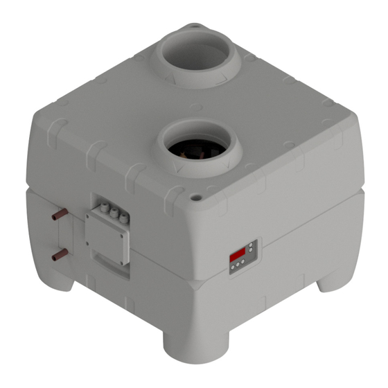
Page 7: Dimensions
2 Dimensions General arrangement METROAIR AQUA HPM All dimensions in mm. 1 Inlet air Ø 160 mm 2 Outlet air Ø 160 mm 3 Cold water connection Ø15 4 Hot water connection Ø15 5 Circuit board 6 Electrical junction box 7 Condensate drain 3/4”... -
Page 8: About The Product
3.3 Product description avoid accidents. The METROAIR AQUA HPM is a hot water heat pump, ready made for installation. It has been designed for domestic hot water application but can also be used for e.g. space heating applications. It consists of cabinet, components for refrigerant, air and water circuits as well as control panel, and control and monitoring equipment designed for automatic operation. -
Page 9: Technical Data
3.5 Technical data Dimensions (LxWxH) 580x575x508 Weight Air duct connections Ø160 Water connections (compression fittings) Ø15 Condensate outlet (hose connection) “ Maximum allowed water pressure Maximum allowed water temperature in tank °C Allowed flow range external circulation pump I/hr 200-600 (not included) Refrigerant/quantity -/kg... -
Page 10: Refrigerant Circuit - Description
3 About the product 3.7 Refrigerant circuit – description The cooling system is optimized for extracting the heat from the inlet air. Via the cooling system the extracted heat is transferred to the water. The process is only possible with the addition of additional external energy in the compressor. -
Page 11: Requirements For The Water Circuit
3.8 Requirements for the water circuit The water circuit must be constructed in accordance with local norms and standards. The water used must be of drinking water quality when charged to the system. Material compatibility in the whole system must be ensured. The pipe sizes for on-site installation shall be defined based on the available water pressure as well as the expected pressure loss in the pipe system. -
Page 12: Water Circuit - Diagram
3 About the product 3.8.1 Water circuit - diagram The HPM heats up the water by the principle of repeatable circulations to reach set point tem- perature, typically, 5-15 passes to fully heat op a water tank starting with cold water. Therefore the following should be observed during installation: - The hot water inlet from the heat pump shall be placed, e.g., 1/3 down from the top to ensure that hot water is available for use while the heat pumpe heats up the lower 2/3 of the water... -
Page 13: Electrical Diagram Optima 172 Control
3.9 Electrical diagram Optima 172 Control Q1=1,6A Q2=5A MA4- Magnetventil afrimning Magnetventile Abtau Solonoid valve Defrost Nettilslutning 1x230V 50Hz sikring max. 13 Amp Excluded Included end main: 1x230V 50Hz fuse mx. 13 Amp Netzende: 1x230V 50Hz 80°C sicherung max 13 Amp El-patron 1,5kW Electric heating element 1,5kW Heizstab 1,5kW... -
Page 14: Fan Capacity
3 About the product 3.10 Fan capacity 250,0 100% 200,0 150,0 100,0 50,0 Air volume flow [m It is recommended to keep the external pressure loss below 100 Pa. -
Page 15: Before Installation And Start Up
4.1.2 Electrical circuit – safety instructions When connecting the METROAIR AQUA HPM to the power supply, the national rules and norms must be adhered to. Possible additional requirements posed by the local energy supplier must also be followed. -
Page 16: Installation
1. Remove the top packaging. 2. Removed the compressor transportation fixtures (2 pieces, shown by arrows) 3. Lift the METROAIR AQUA HPM from the cardboard base and place it on its final destination, e.g., a shelf or disignated wall brackets. -
Page 17: Water Connections
5.4 Connection of condensate drain While the METROAIR AQUA HPM is running, condensate will form, which is to be discharged to the sewage drain via the condensate drain pipein the bottom of the unit. The quantity of condensate depends upon the humidity of the air fed to the METROAIR AQUA. -
Page 18: Air Intake, Air Exhaust And Connections
Temperature sensor T8 is the sensor which controls the start/stop of the heat pump. The T8 The METROAIR AQUA HPM sensor shall be installed at such height on the water tank that there is sufficent hot back-up must always be disconnected from... -
Page 19: Commissioning
Power up the unit. A counter displays the numbers 1 to 9 followed by display of the controller model (172) for 3 sec. and the software version for 3 sec. Then the top of water tank temperature is displayed and the unit engages operation. The METROAIR AQUA HPM is now ready for use. -
Page 20: Controls And Operations
7 Controls and Operations 7.1 Control panel Optima 172 The METROAIR AQUA HPM is delivered with an Optima 172 control with factory settings so that the heat pump is ready for operation without additional adjustments. The factory settings are default settings that should be adjusted in accordance to the operational needs and user requirements in order to achieve optimal performance and utilisation of the system. - Page 21 P2: Controlling the auxilary electrical heater The “electric heater”-key is pressed and held. Then the setting can be changed with the arrow keys. At outside temperatures below 0°C it may be beneficial to use the electrical heater as a supple- ment for heating the domestic water.
-
Page 22: Display View (Main Menu)
7 Controls and Operations 7.3.1 Display view (main menu) The display show the various temperatures by pressing the arrow keys. Press until the number of the sensor of the desired temperature appears. After approximately 3 seconds the temperature is displayed. The relevant temperature is displayed for about 30 seconds before the display goes back to normal view. - Page 23 E2: T9 temperature set point Here a temperature can be set which can be used in connection with menu item E19 and temperature sensor T9. This is a separate sensor, which is not part of standard delivery. See E19=2, 4 or 5 for further description. Options: 0-30°C Factory setting: 21°C E6: Anti-legionella - week day...
- Page 24 7 Controls and Operations E13: Floor heating temperature Here a temperature is set, which can be used in connection with menu item E19=2, i.e., the minimum temperature, at which the circulation pump for the floor heating starts. If the temperature T8 (water tank) is less than the value set at menu point E13, the circulation pump stops.
- Page 25 E18: Number of hours Setting of number of hours for continuous run at fan speed mode 3 before automatically switching back to mode 2. This option is used by the menu item E17=1. Options: 1-10 hours Factory setting: 3 hours E19: Extra function This function controls relay R9: Solar collector, additional heat sources, heat sink, or damper control.
- Page 26 7 Controls and Operations (water tank) + menu item E20 (solar collector hysteresis). When the pump (relay R9) is activated, the heat pump and the auxilary electrical heater relay switches off. After the pump (relay R9) is deactivated the following happens after 15 min: •...
- Page 27 This value specifies the maximum evaporator temperature (T6) allowed. This prevents overload- ing of the cooling system at high ambient temperatures. Options: 0-30 °C Factory setting: 25 °C E25: Fan speed mode 1 + 2 If extraction of air for a longer period of time is required, mode 2 (P1) can be chosen. The fan will now run, until it is change to a different mode.
- Page 28 7 Control and Operations The required time (minutes) where the T10 input must be higher than the E31 set point before the heat pump starts in PV mode. This parameter allows filtering of input power and avoidance of heat pump starts on short spikes of excess PV power.
- Page 29 E49: Screen saver Here you can select the screen saver: 1: Blank display. A point flashes to show that the system is powered. 2: Water temperature T7 (water tank, top) is displayed. 3: The time is displayed. Options: 1-3 Factory setting: 2 E50: Internal clock hours Here the hours of the clock are set.
- Page 30 7 Control and Operations Options: 0-23 hours Factory setting: 6 hours E60: Temperature difference between T5 and T6 This is an operational safety feature which indicates that the heat pump is not running properly, potentially lacking refrigerant or indicating that the solonoid valve does not close properly. If the T6 temperature (evaporator) is higher than the T5 temperature (before evaporator) + the value set in menu point E-0 after one hour with the compressor in operation, the compressor will turn off.
-
Page 31: Table For Set Points
7.5 Table for set points Factory setting Date: Date: E0: Factory settings E2: T9 temperature set point E6: Anti-legionella - week day E7: Anti-legionella – start time E8: Anti-legionella function E9: Operation in cold surroundings ON/OFF E10: Operation in cold surroundings temperature E13: Floor heating temperature E15: Hygrostat / stop system E16: Minimum air flow... -
Page 32: Functional Description
7 Control and Operations 7.6 Table for defrosting T5 before evaporator °C T6 evaporator °C The defrost function runs according to the table for defrosting above. If the T5 temperature (before evaporator) is equal to a temperature in the table then the defrosting will start, if the corresponding T6 temperature (evaporator) drops below the temperature in the table. -
Page 33: Controlling Domestic Hot Water Heat Pump With Optima 170
7.7.1 Water heating When tapping hot water, cold water is supplied to bottom of the water tank. A sensor measures the temperature in the water tank. When the temperature has dropped 5°C below the set temperature, the compressor starts and the fan ventilates air through the evaporator. When the water is heated to the set temperature, the compressor (and fan) stops again. - Page 34 7 Control and Operations 7.7.4 Extra heating capacity If a situation arises where the domestic hot water heat pump is not able to provide enough hot water, it is possible to activate an auxilary electrical heater. About twice as much water can now be heated in the same period of time.
- Page 35 The call for heating (low water temperatures) can be suppressed during the sunny hours (only allowing for operation on PV power) and released for normal mode operation during user defined evening and night times. This is done by the existing low tariff function. [fig 21] The figures below illustrates typical installation options.
-
Page 36: Safety Features
7 Control and Operations 7.7.6 Timer function The timer function includes a 24 hours clock plus week days (1-7). Two different low tariff periods can be defined, working days and weekends. Also, the day and time for anti-legionella control can be set. 7.8 Safety features 7.8.1 High pressure switch In order to ensure that the compressor does not run beyond its operating envelope there is a... -
Page 37: Maintenance
8 Maintenance To achieve optimal performance, please observe the points below. Before the unit is opened, disconnect the power/unplug and wait until the fan has stopped. A few days after the initial setup and start-up, check the installation for leaks in the water installation or blockage of the condensate drain. -
Page 38: Disassembly/Decommissioning
9 Disassembly/decommissioning The following must be done. • Disconnected the unit from the power mains - i.e. the electrical wires are removed. • Close the cold water supply and attach a hose to the drain valve, so that water from the tank can run to the nearest drain. -
Page 39: Troubleshooting
The installer, from which the unit was purchased. • After the warranty period (2 years ->): The installer from which the unit was purchased or METRO THERM Partners. Please have data from name plate ready (silver plate on the unit). -
Page 40: Warranty Provisions
- The product has to be located so that it can be serviced without obstacles. If the product is located in a way that is hard to access, METRO THERM disclaim all obligations with respect to extra expenses this may cause. -
Page 41: Declaration Of Conformity
12 Declaration of conformity... -
Page 42: Product And Installer Information
13 Product and installer information Installed model: Serial number: Accessories: Installers Pipe installation Date: Company: Name: Phone number: Electrical installation Date: Company: Name: Phone number: Commissioning Date: Company: Name: Phone number:... - Page 44 MET RO TH ERM A/S R UND INSVEJ 5 5 32 00 H ELSINGE IN FO@ME TROTH ER M. DK WWW.MET ROTH ERM.D K...
Need help?
Do you have a question about the METROAIR AQUA HPM and is the answer not in the manual?
Questions and answers