
Related Manuals for Opsytec Dr. Grobel BS-03


Summary of Contents for Opsytec Dr. Grobel BS-03
- Page 1 Irradiation Chamber BS-03 Manual Opsytec Dr. Gröbel GmbH Am Hardtwald 6-8 D-76275 Ettlingen Phone: +49(0)7243 / 9 47 83-50 info@opsytec.com...
-
Page 2: Table Of Contents
1 Table of Contents Table of Contents Table of Contents .......................2 Preface ..........................4 Quick start guide ........................5 Guidelines and standards ....................7 Identification ........................8 Manufacturer, Ordering of Spares and Customer Service ........8 Change History ......................8 Copyright ........................8 Identification of the Device..................8 Intended Use ......................9 Foreseeable Misuse .................... - Page 3 1 Table of Contents UV-MAT operation ......................52 12.1 Switching on ......................53 12.2 Switching off ......................53 12.3 Settings menu ......................58 12.4 Dimming menu ......................63 12.5 Internal settings ...................... 64 USB logging* and REMOTE operation*................ 66 13.1 Software Installation ....................
-
Page 4: Preface
2 Preface Preface Dear Customer! Thank you for choosing a product manufactured by us! Please take your time to read this manual carefully. Please pay special attention to the safety instructions. This is the condition for safe handling and safe operation of the system and its components. If you have any questions that you do not find answered in this manual, please call us and we will be pleased to assist you. -
Page 5: Quick Start Guide
3 Quick start guide Quick start guide The quick guide should demonstrate the installation and some of the system functions to trained personnel. You will find the detailed instructions on page 28. Please pay special attention to the safety instructions given in the complete manual. As an alternative to the UV-MAT Touch, we offer the UV-MAT. - Page 6 3 Quick start guide Select the dose-controlled or time-controlled operating mode. • • Set the desired dose or time. Note the assignment of the sensors and the lamp group. If, for example, a UVA sensor is connected to channel 1, UVA lamps must also be inserted in lamp group 1.
-
Page 7: Guidelines And Standards
4 Guidelines and standards Guidelines and standards The system is machinery under Annex II A of the Machinery Directive and is therefore delivered with a declaration of conformity and with a CE mark (in accordance with the Machinery Directive). Directives EC Directives 06/42/EC (Machinery) (partially observed) 2014/30/EC (EMC) -
Page 8: Identification
5 Identification Identification 5.1 Manufacturer, Ordering of Spares and Customer Service Opsytec Dr. Gröbel GmbH Am Hardtwald 6-8 D – 76275 Ettlingen Tel.: +49(0)7243 / 9 47 83-50 info@opsytec.com www.opsytec.com 5.2 Change History We reserve the right to make changes in content. Opsytec Dr. Gröbel GmbH is not liable for any errors in this documentation. -
Page 9: Intended Use
5 Identification 5.5 Intended Use The irradiation chamber is a controlled radiation-source for different UV applications like • Irradiation of bacterial and cell cultures • PCB and wafer irradiation & cleaning • Accelerated aging of plastics and similar materials with UV •... -
Page 10: Foreseeable Misuse
5 Identification 5.6 Foreseeable Misuse The following is considered foreseeable misuse: • Operation of the device without safety devices and equipment. • Activities of uninstructed personnel on the device. • Non-compliance with the operating instructions of the owner/operator. • Ignoring of the operating manual. •... -
Page 11: General
6 General General IMPORTANT SAFETY PRECAUTIONS WARNING - Always observe the following basic precautions when using electrical equipment: (a) Read all instructions before using the equipment. b) This equipment is to be used only by qualified and trained personnel. Refer to the training section in this manual. c) Know how to turn off the product. - Page 12 6 General For a simple description, the above mentioned components are collectively referred to as system.
-
Page 13: Information About The Symbols
6 General 6.2 Information about the Symbols 6.2.1 Safety Instructions In this manual, safety information is indicated by means of symbols. Safety information is preceded by signal words that indicate the scope of risk. To avoid accidents and damage to persons or property, always follow the information and act prudently. - Page 14 6 General 6.2.3 Warning Signs Warning of optical radiation (such as UV, IR, or visible radiation) Warning of hot surface! Warning of electricity! 6.2.4 Attention Wear eye protection! Opaque eye protection must be worn! Disconnect mains plug from electrical outlet! Disconnect before carrying out maintenance or repair Use hand protection! Wear foot protection!
- Page 15 6 General 6.2.5 Optional functions Optional functions, not available for every system...
-
Page 16: Owner/Operator Information
6 General 6.3 Owner/Operator Information The System is used in the commercial sector. The owner/operator of the system is therefore subject to the legal obligations concerning work safety. In addition to the safety information in this manual, the generally applicable regulations valid for the application area of the system concerning safety, prevention of accidents and for protection of the environment must be noted and complied with. - Page 17 6 General Personnel Requirements The maximum number of qualified professionals allowed to be at the site at the same time: 2 6.4.1 Qualifications WARNING Risk of injury when personnel are insufficiently qualified! If unqualified personnel carries out work on the system or stays in the danger area of the system risks arise that may cause severe injuries and serious material damage.
- Page 18 6 General In addition, due to their technical training, knowledge and experience and knowledge of the relevant standards and regulations, they are able to carry out work they have been assigned and to recognize and avoid possible risks independently. 6.4.4 Operators Operators use and operate the system in the scope of the intended use.
-
Page 19: Personal Protective Equipment
6 General 6.5 Personal Protective Equipment The purpose of personal protective equipment is to protect the personnel from risks that might affect his safety or health when working. When executing various activities on and with the system, the personnel must wear personal protective equipment. -
Page 20: Safety Information And Residual Risk
7 Safety Information and Residual Risk Safety Information and Residual Risk 7.1 General The system is state-of-the-art and has been built in compliance with recognized safety regulations. Nonetheless, its use may constitute risks for life and limb of the operating and repair personnel (service personnel) or third parties or impairments to the machine. -
Page 21: Safety Information Concerning Normal Operation
7 Safety Information and Residual Risk 7.2 Safety Information Concerning Normal Operation DANGER Danger to life Danger to life occurs when the system is operated with defective or absent safety devices. The system should be operated only when all protective devices •... - Page 22 7 Safety Information and Residual Risk Please note that the manufacturer of this device accepts no liability for the quality of the irradiation result of the irradiated material, as this depends on many factors. Always check the irradiation result after irradiation and adjust the irradiation if necessary.
-
Page 23: Radiation Safety
7 Safety Information and Residual Risk 7.3 Radiation Safety WARNING Risk of eye injury UV-radiation is harmful! Always wear suitable safety glasses. Avoid direct exposition. This product is equipped with UV and visible high intensity LAMPs. There is a risk of photo-chemical or thermal damage of the eye, retinal damage of the eye and erythema. - Page 24 7 Safety Information and Residual Risk CAUTION Risk of Damage Skin fat and dirt are absorbent in the UV and visible spectral • range. Avoid fingerprints on the optically components, sensor surfaces, • Lamps and reflectors. If necessary, the components must be cleaned carefully with Isopropyl.
-
Page 25: System Description
8 System Description System Description The irradiation chamber is a controlled radiation-source. 20 UV-tubes of 15 Watts each can be installed. These tubes can be in the spectral range of UVA, UVB, UVC or daylight. Two spectral ranges can be combined and both types can be turned off separately. The external dose controller UV-MAT and the UV-sensors allow independent control of the dose of the 2 possible types of UV-irradiation. - Page 26 8 System Description Rear view and ventilation concept: Pos. Designation Pos. Designation Irradiation chamber Connector for UV-MAT Cable feedthrough Air inlet for samples Air outlets Connector for mains Pos. Designation Pos. Designation UV-Mat Touch UV-Mat Pos. Designation Pos. Designation Sensor...
- Page 27 8 System Description The UV-MAT unit contains the power supply, the microcontroller system with display and keyboard and the output controls. The sensor is connected to the backside of the UV-MAT unit. The sensors are adapted to the lamps, meaning UVA+ sensor for UVA lamps for example. The sensors are cosine corrected.
-
Page 28: Commissioning
9 Commissioning Commissioning • Unpack all components and remove the packaging materials. WARNING Risk of injury! High Weight! Always carry the system with two persons. The irradiation chamber is delivered with UV lamps not mounted. You must install • these. The irradiation chamber has two lamp groups (even and odd lamps). Always alternate the lamps when using two different types. - Page 29 9 Commissioning WARNING Risk of damage To prevent thermal overheating, sufficient ventilation must be ensured at all times. Take special care that the ventilation openings are not covered during operation and that sufficient cooling is ensured.
-
Page 30: Installing And Replacing A Lamp
9 Commissioning 9.1 Installing and replacing a lamp The useful life of UV amalgam low pressure lamps depends on the system design and the mode of operation (ON-OFF switching cycles, cooling, and pollution). Frequent switching the irradiation chamber on / off can lead to a significantly reduced useful lifetime. -
Page 31: Attenuator
9 Commissioning When replacing the lamps completely, it is advisable to first remove all the lamps and • then replace them. • Reconnect the irradiation chamber to the supply voltage. 9.2 Attenuator* Two types of attenuators are available: 1. lamp attenuators* that are slid over the lamps (1). 2. -
Page 32: Commissioning And Use Of Inter Box
9 Commissioning 9.3 Commissioning and Use of inter box* If your chamber is equipped with an inert box: Unpack inert box and clean front window with ISOPROPANOL alcohol. Air-inlet and air-outlet can be changed depending on customer needs. Pull the connecting hoses for the N2 input and N2 output through the rear openings of the irradiation chamber. -
Page 33: Operating
10 Operating 10 Operating The irradiation chamber is switched on together with the UV-MAT / UV-MAT TOUCH using the power switch on the front of the irradiation chamber. CAUTION Wear gloves when working in the BS-02 irradiation chamber. CAUTION The equipment is equipped with UV lamps. There is a risk of photochemical damage to the eye, retinal damage and erythema. - Page 34 10 Operating Set the desired dose or time. For this purpose, note the assignment of the sensors • and the lamp group. If, for example, a UVA sensor is connected to channel 1, UVA lamps must also be inserted in lamp group 1. Start the irradiation by main switch, timer, operation mode switch or UV-MAT, •...
-
Page 35: Operation With A Uv-Mat Touch
11 Operation with a UV-Mat Touch 11 Operation with a UV-Mat Touch The UV-Mat Touch is characterized by its capacitive touch display and the extended functions compared UV-MAT. addition, remote control possible. As an alternative to the UV-MAT Touch, we offer the UV-MAT. This chapter only refers to the operation on the UV-MAT Touch. -
Page 36: Introduction To The User Interface
11 Operation with a UV-Mat Touch When the device is switched on for the first time, the date and time should be checked and set if necessary. Turn off the system at the switch on the front panel. The operating mode and the set power are saved permanently. After a restart, the last operating mode is selected (exception: settings). -
Page 37: Setting The Setpoints
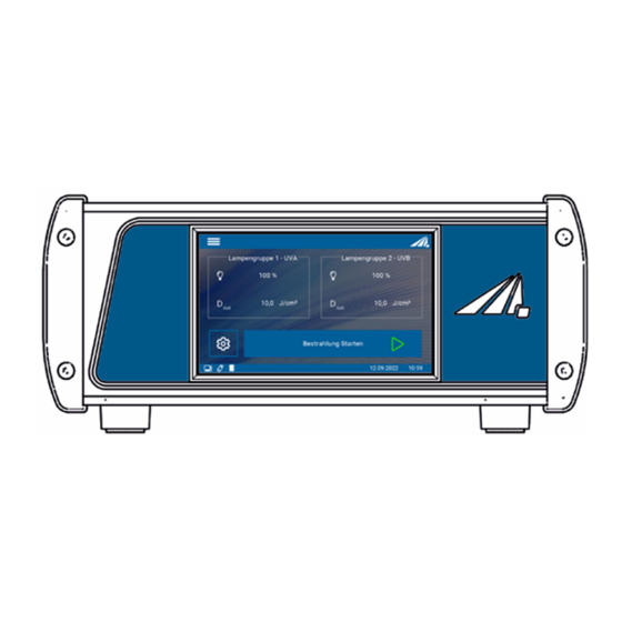
11 Operation with a UV-Mat Touch The different menus Measurement screens are explained in the following chapter. Here the symbols mean: Symbol Function Menu Settings menu Start irradiation USB connection to a PC USB stick plugged Sensor temperature Sensor designation Sensor channel Sensor error Irradiation chamber door is closed... - Page 38 11 Operation with a UV-Mat Touch This keystroke takes you directly to the settings menu. Both lamp groups can be found under the menu item "Dimming". It is possible to set each lamp group separately or both to the same value.
- Page 39 11 Operation with a UV-Mat Touch 11.3.2 Operating mode There are two operating modes to control the lamp duty cycle. One is via the time and the other is via the dose. In dose-controlled mode, the irradiation is automatically stopped when the target dose is reached.
-
Page 40: During Irradiation
11 Operation with a UV-Mat Touch 11.3.2.2 Time operating mode In time-controlled mode, you can set the duration of irradiation for each channel: To do this, select the "Time setting" menu item. If "Time setting" is not displayed, please first select "Time controlled"... - Page 41 11 Operation with a UV-Mat Touch Displays the target time. After this time, the irradiation is terminated. When a maximum dose is set, the target dose is set. When the dose is reached, the irradiation is terminated. The progress bar shows the current progress Displays the current irradiation time Irradiation is canceled.
- Page 42 11 Operation with a UV-Mat Touch 11.4.2 Dimming display In the Dimming display, the individual lamp groups can be dimmed independently of each other. Adjustment in individual steps is possible with a single click. Quick adjustment by holding the button. 11.4.3 Scope display This display is used to graphically show the progress of the irradiation.
-
Page 43: After Irradiation
11 Operation with a UV-Mat Touch Display of the sensors and the assigned colors 11.5 After irradiation The end of the irradiation is indicated by the full green progress bar and the display "FINISHED". The current values can now be read off. In addition, it is possible to restart the irradiation with the same settings or return to the main screen. -
Page 44: User Settings
11 Operation with a UV-Mat Touch Type 814461 Serial number 00135 Calibration date10 .05.2019 Unit Wavelength range380 - 780 nm Measuring range0-2000 klx [CH2 Info] Sensor type1x , UV-C, RM-Digital Sensor Type 814410 Serial number 00115 Calibration date10 .05.2019 Unit W/cm2 Wavelength range200 - 280 nm... - Page 45 11 Operation with a UV-Mat Touch The irradiation dose is automatically summed up if it is higher than the threshold irradiance. This minimizes possible small offset errors. The chamber factor is used to calculate and output the irradiance at a different position (than the sensor position). Further chamber factors (for unconnected) sensors can be seen here.
- Page 46 11 Operation with a UV-Mat Touch 11.7.3 Time The RMD Touch has a real-time clock. You can set the real-time clock in the "Date / Time" menu. The real-time clock is set automatically by connecting the device to the PC software or can be set in the Time menu.
- Page 47 11 Operation with a UV-Mat Touch no password protection, all menus are active All settings are password protected only the "User menu" is password protected. Irradiation and dimming can be changed. The password is: 7243 11.7.5 Record The UV-Mat Touch can create a protocol of the irradiation. There are various setting options here.
- Page 48 11 Operation with a UV-Mat Touch 11.7.6 Fan It is possible to adjust the fan during and outside irradiation. Thus, the volume alone can be reduced. Fan power in standby / without irradiation Fan power during irradiation The fan continues to run for the set time after irradiation with the irradiation power The fan runs for the set time after the start of irradiation still with the standby power...
-
Page 49: Information
11 Operation with a UV-Mat Touch 11.7.9 Firmware update The firmware of the device can be updated with a Windows PC. Please contact the manufacturer for this. 11.8 Information Sensor-specific and device-specific information can be called up under the Information menu item. - Page 50 11 Operation with a UV-Mat Touch Display of information about the UV-MAT Touch.
-
Page 51: Error Messages
11 Operation with a UV-Mat Touch 11.9 Error messages The system issues various error messages. It is possible to react to them in different ways. During irradiation, the door was opened. Irradiation automatically interrupted and the lamps switched off. Cancel: Irradiation is canceled and the control returns to the main screen. -
Page 52: Uv-Mat Operation
12 UV-MAT operation 12 UV-MAT operation As an alternative to the UV-MAT, we offer the UV-MAT Touch. This chapter only refers to operation on the UV-MAT. After starting the device, the logo first appears on the display. Then the device is in standby and the main menu is displayed. -
Page 53: Switching On
12 UV-MAT operation 12.1 Switching on Switch on the control unit at the front switch. After starting the device, the logo appears on the display followed by a short self-test. The device is then in standby and the menu is displayed. Main menu Start Radiation Operating Mode... - Page 54 12 UV-MAT operation Start / Stop Radiation Start an irradiation by selecting “Start Radiation” and press . In time controlled operation mode the current irradiation time and end time are displayed in the form DD:HH:MM:SS. In dose controlled operation mode the current irradiance in mW/cm², the actual irradiation time, the current dose (Is:) and the target dose (Set:) are displayed: Ch2 1&2 DIM 1&2 Ch2 1&2 DIM 1&2...
- Page 55 12 UV-MAT operation 12.2.1 Operation Mode In dose-controlled mode, irradiation is automatically stopped when the target dose is reached. In time-controlled mode (timer), the irradiation time is controlled. Only the irradiation time is shown on the display. No sensor is required for time-controlled irradiation, so that the irradiation chamber can continue to be used, e.g., during recalibration of the sensor.
- Page 56 12 UV-MAT operation 12.2.2 Timer mode In the menu “Irradiation Time” you can set the irradiation time for the timer. Therefore select menu item “Set time”. If “Set time” is not displayed, please choose “Time controlled” in menu “Operation Mode” first. The irradiation time can be set for CH1 and CH2 together or individually.
- Page 57 12 UV-MAT operation 12.2.3 Dose controlled mode Select operation mode dose controlled. Confirm by with or . With you can cancel your input and go back to main menu. In dose controlled mode the irradiation time is automatically controlled and stops if the desired dose is reached.
-
Page 58: Settings Menu
12 UV-MAT operation mW/cm² and J/cm² are automatically calculated. Stop an irradiation by pressing for at least 2 seconds. 12.3 Settings menu Using this menu you can set the system settings. Settings Channel control Chamber factor Units Language Status Sensor Info ... - Page 59 12 UV-MAT operation Note, that the channel control is displayed during irradiation in the upper right corner. Here the icons have e.g. the following meaning: CH1 and CH2 are ON and controlled separately CH1 and CH2 are OFF and controlled separately CH1 and CH2 on and controlled by Sensor 1 CH1 and CH2 on and controlled by Sensor 2 The signal lamps on the front of the irradiation system also show the...
- Page 60 12 UV-MAT operation 12.3.2 Chamber factor In this submenu the sensor specific adjustments are placed. It is possible to do the sensor calibration and set the upper and lower limits. In all three submenu points you have to decide first for which sensor port you want to do the adjustment, if Your UV-Mat version is capable of more than one sensor.
- Page 61 12 UV-MAT operation 12.3.3 Units Unit in which the measured values of the sensors are displayed. This is a setting for the sensor that applies to the measured channel (including dose). Irradiance mW/cm² => mJ/cm² • W/m² => J/m² • •...
- Page 62 12 UV-MAT operation 12.3.6 Sensor Info Sensor-specific information can be called up under the menu item. Only connected sensors appear in the info menu. Display information about the sensor. If no sensor is connected, this menu item is not displayed. 12.3.7 USB-Settings This meue item enables or disables USB output and control: USB-Settings...
-
Page 63: Dimming Menu
12 UV-MAT operation 12.4 Dimming menu You can change the dimming setting in the main menu via the Dimming menu item. It is possible to set a dimming value between 10% and 100% individually for each lamp group. Note: The dose control on the UV-MAT does not fall back on the dimming setting, but ends the irradiation at the dose reached. -
Page 64: Internal Settings
12 UV-MAT operation 12.5 Internal settings Using this menu you can set the system settings. Therefore enter the PIN code, see chapter technical data, must be entered. Enter password: Hours CH1: 1:00:00 Hours CH2: 5:00:00 On this screen you will see the operation hours for each channel. The format is hours:minutes:seconds. - Page 65 12 UV-MAT operation 12.5.2 Operating hours The user may reset the lamps operating hours using the menu item. Reset must be confirmed by pressing . Note that the displayed operating hours are only stored if an irradiation is stopped by UV-MAT. If the UV-MAT / irradiation chamber is switched off during irradiation the operating hours aren’t stored and so faulty.
-
Page 66: Usb Logging* And Remote Operation
13 USB logging* and REMOTE operation*. 13 USB logging* and REMOTE operation*. The UV-MAT automatically transmits all data when USB is set to active. The communication takes place as ASCII communication. Communication is available after initialization. Depending on the version, initialization may take a few seconds. Definitions: •... -
Page 67: Software Installation
13 USB logging* and REMOTE operation*. Remote operation is required if the UV-MAT and the irradiation chamber are to be controlled via a USB interface. Remote operation is selected in the UV-MAT settings. In remote mode, operation on the device is not possible. Remote operation is selected in the UV-MAT settings. -
Page 68: Software - Uv-Mat Control For Uv-Mat Touch
14 Software – UV-MAT Control for UV-MAT Touch* 14 Software – UV-MAT Control for UV-MAT Touch* The software "UV-MAT Control" is used to control the irradiation chamber with UV-MAT TOUCH by PC. The software makes it possible: Switching lamp channels on and off •... - Page 69 14 Software – UV-MAT Control for UV-MAT Touch* The left area of the software is for control and monitoring. Here an overview table with all services, times and dose values for the channels is displayed. The table is used to select the channels, to display the currently set power intensity and to display the channel status.
-
Page 70: Working With The Software
14 Software – UV-MAT Control for UV-MAT Touch* Software taskbar At the bottom of the software is a bar with various functions: The right part of the bar is used to display errors and messages Errors and messages appear in the display for 3 s, errors are highlighted in red. The last ten messages are displayed here while the mouse pointer is resting. - Page 71 14 Software – UV-MAT Control for UV-MAT Touch* testUVMATControll.csv Date (dd.mm.yyyy); 29.48.2020 Software version number; 1.0.0.0 Number of Steps; 6 ****************************** power channel 1; setpoint channel 1; operating mode 1; power channel 2; setpoint channel 2; operating mode 2; ****************************** 2;5;s;8;5;mJ/cm²;...
-
Page 72: Technical Data
15 Technical Data 15 Technical Data General data BS-03 +15 to 30 °C Ambient temperature + 5 to 60 °C Storage temperature < 80% non-condensing Humidity Cooling Air cooling Maximum housing temperature < 60 °C ~25-30 °C +/- 5 °C. - Page 73 15 Technical Data General data UV-MAT PC interface USB 2.0 Virtual Serial Port Baud: 115200 Databits: 8 Parity: None Stop Bits: 1 Display UV-MAT graphic, 128 x 64 px Display UV-MAT Touch Capacitive touch display Dosisberechnung for all irradiance measurements >...
- Page 74 15 Technical Data TECHNICAL DATA SENSORS (typical) Measuring range See type, typically 0 - 100 mW/cm² to 0 - 10 W/cm² Resolution 0.01 mW/cm² Illuminance measurementsb. See type, typically 0 - 500,000 lx Dynamic range up to 10 AD conversion 24 bit Dimensions Ø...
- Page 75 15 Technical Data D-65: LT 15W/865 VIX: cool white Power 15 W each Total number of lamps Lamp groups Lamp group 1: from left positions 1-3-5-7 (1 marked) Lamp group 2: from left positions 2-4-6-8 (2 marked) Typical distribution intensity The energy distribution on the drawer sheet metal has the following distribution: The front edge of drawer is at the lower end of the diagram.
- Page 76 15 Technical Data Lamda [nm] Lamp spectra UVB Lamda [nm]...
- Page 77 15 Technical Data Lamp spectra UVC Lamda [nm] Lamp spectra D65 Lamda [nm]...
-
Page 78: Maintenance
16 Maintenance 16 Maintenance This chapter is intended for qualified users with maintenance tasks. The system is largely maintenance-free. Clean the optical components only if necessary. Turn the irradiation chamber off with the power switch. Disconnect power plug from mains. The BS-02 is a combined system that needs only cleaning, lamp exchange and recalibration as maintenance. - Page 79 16 Maintenance Recommended No. Maintenance Item Procedure frequency Cleaning of bottom side from process chamber. Overall checking Accumulated dust clean-up, rust check, peeled paint and cleaning of the Semi-Annual check, leak, broken switch, and damaged covers, machine otherwise replace it. 1.
-
Page 80: Calibration
16 Maintenance Only carry out cleaning work on the sensor as required. This gives you the best possible stability. Clean exclusively with isopropanol (UV-IR-GRADE), with oil-free compressed air or with clean, lint-free cloths. Wear clean, lint-free gloves. Apply the cleaning agent only to the cloth, only moisten. The cleaning agent could get inside and cause damage to property. -
Page 81: Declaration Of Conformity
Country: Deutschland Product: Irradiation chamber with UV lamps, UV dose controller UV-MAT and sensor(s) Type designation: BS-03 Type number: 860 903 XXXX, 860 901 860 920 XXXX, 860 930 XXXX 814 4XX XXXX, 8608XX, 87000X The manufacturer hereby declares that we have developed, designed and manufactured the above product(s) -
Page 82: Spare Parts
Air outlet filter set BS-03-AOF Air outlet cover set BS-03-AOCS Connector end caps for cables BS-03-EC Bottom plate BS-03-BP Front door with internal mirror BS-03 BS-03-Door Door contact 860801L-DC UV-MAT specify serial number Sensor See sensor type Sensor recalibration 710001... -
Page 83: Notes
19 NOTES 19 NOTES CAUTION THIS MANUAL CONTAINS IMPORTANT SAFETY INSTRUCTIONS. KEEP THESE INSTRUCTIONS IN A SAFE PLACE.
Need help?
Do you have a question about the BS-03 and is the answer not in the manual?
Questions and answers