
Related Manuals for Opsytec Dr. Grobel UV LED LedControl DC


Summary of Contents for Opsytec Dr. Grobel UV LED LedControl DC
- Page 1 UV LED LedControl DC manual Version 3.0.2 Opsytec Dr. Gröbel GmbH Am Hardtwald 6-8 D-76275 Ettlingen info@opsytec.de www.opsytec.de Telefon: +49(0)7243 / 9 47 83-50...
-
Page 2: Table Of Contents
1 Inhaltsverzeichnis Inhaltsverzeichnis Inhaltsverzeichnis ......................2 Foreword ..........................4 Guidelines and standards ....................5 Identification ........................6 Manufacturer, ordering spare parts and after-sales service ........6 Change history ......................6 Copyright ........................6 Device identifier ......................7 Intended use ......................7 General ..........................8 Information about this Manual ...................8 Information about the Symbols ................10 Owner/Operator Information ................... -
Page 3: Inhaltsverzeichnis
1 Inhaltsverzeichnis Fehler / Error ........................45 Software - LedControl Remote for programming interface*........46 12.1 Install software ......................48 12.2 Working with the software..................48 12.3 Activate LED channels .................... 49 12.4 Switching LED channels on and off ................ 50 12.5 Change intensity ..................... -
Page 4: Foreword
2 Foreword Foreword Dear customer! Thank you for choosing a product made by us! Please take some time to read this manual carefully. Please pay special attention to the safety instructions. This is the condition for safe handling and operation of the system and its components. If you have any questions that are not answered in this manual, please feel free to call us. -
Page 5: Guidelines And Standards
3 Guidelines and standards Guidelines and standards The system is machinery under Annex II A of the Machinery Directive and is therefore delivered with a declaration of conformity and with a CE mark (in accordance with the Machinery Directive). Directives EC Directives 06/42/EC (Machinery) (partially observed) 2014/30/EC (EMC) -
Page 6: Identification
4 Identification Identification 4.1 Manufacturer, ordering spare parts and after-sales service Opsytec Dr. Gröbel GmbH Am Hardtwald 6-8 D - 76275 Ettlingen Tel.: +49(0)7243 / 9 47 83-50 info@opsytec.de www.opsytec.de 4.2 Change history We reserve the right to make changes to the content. Opsytec Dr. Gröbel GmbH is not liable for any errors in this documentation. -
Page 7: Device Identifier
4 Identification 4.4 Device identifier Data for internal use: Description of the machine: LedControl UV LED System Year of manufacture: ......Machine no......Project no......4.5 Intended use The LED system is a high-intensity light source for curing UV adhesives and potting compounds or similar products. -
Page 8: General
5 General General IMPORTANT SAFETY PRECAUTIONS WARNING - Always observe the following basic precautions when using electrical equipment: (a) Read all instructions before using the equipment. b) This equipment is to be used only by qualified and trained personnel. Refer to the training section in this manual. c) Know how to turn off the product. - Page 9 5 General For a simple description, the above mentioned components are collectively referred to as system.
-
Page 10: Information About The Symbols
5 General 5.2 Information about the Symbols 5.2.1 Safety Instructions In this manual, safety information is indicated by means of symbols. Safety information is preceded by signal words that indicate the scope of risk. To avoid accidents and damage to persons or property, always follow the information and act prudently. - Page 11 5 General 5.2.3 Warning Signs Warning of optical radiation (such as UV, IR, or visible radiation) Warning of hot surface! Warning of electricity! 5.2.4 Attention Wear eye protection! Opaque eye protection must be worn! Disconnect mains plug from electrical outlet! Disconnect before carrying out maintenance or repair Use hand protection! Wear foot protection!
- Page 12 5 General 5.2.5 Optional functions Optional functions, not available for every system...
-
Page 13: Owner/Operator Information
5 General 5.3 Owner/Operator Information The System is used in the commercial sector. The owner/operator of the system is therefore subject to the legal obligations concerning work safety. In addition to the safety information in this manual, the generally applicable regulations valid for the application area of the system concerning safety, prevention of accidents and for protection of the environment must be noted and complied with. - Page 14 5 General Personnel Requirements The maximum number of qualified professionals allowed to be at the site at the same time: 2 5.4.1 Qualifications WARNING Risk of injury when personnel are insufficiently qualified! If unqualified personnel carries out work on the system or stays in the danger area of the system risks arise that may cause severe injuries and serious material damage.
- Page 15 5 General 5.4.4 Operators Operators use and operate the system in the scope of the intended use. They are trained by the owner/operator in the work assigned to them and informed about possible risks. 5.4.5 Training and Qualification of Personnel In regular instructions and training, operating personnel must be informed about the special risks when working with and handling the system.
-
Page 16: Personal Protective Equipment
5 General 5.5 Personal Protective Equipment The purpose of personal protective equipment is to protect the personnel from risks that might affect his safety or health when working. When executing various activities on and with the system, the personnel must wear personal protective equipment. -
Page 17: Safety Instructions And Residual Risk
6 Safety instructions and residual risk Safety instructions and residual risk 6.1 General The system is state of the art and has been built in accordance with recognized safety regulations. Nevertheless, its use may pose risks to the life and extremities of the operating and repair personnel (service personnel) or third parties, or impair the machine. -
Page 18: Safety Instructions Relating To Normal Operation
6 Safety instructions and residual risk 6.2 Safety instructions relating to normal operation DANGER Danger to life Danger to life occurs if the system is operated with defective or missing safety devices. The system should only be operated when all safety devices and •... -
Page 19: Radiation Safety
6 Safety instructions and residual risk 6.3 Radiation safety DANGER RISK OF INJURY TO PERSONS Ultraviolet radiation emitted by this product. Avoid exposure. • ALWAYS WEAR PROTECTIVE CLOTHING. EXPOSURE CAN LEAD TO CANCER AND PREMATURE SKIN AGING. ALWAYS WEAR SAFETY GLASSES. FAILURE TO DO SO MAY RESULT IN SEVERE BURNS OR LONG- TERM INJURY TO THE EYE AND SKIN. - Page 20 6 Safety instructions and residual risk WARNING The devices were classified in risk group 3 according to DIN EN 62471:2009- 03 "Photobiological safety of lamps and lamp systems". DIN EN 62471:2009-03 Risk group 3: Luminaires pose a hazard even for transient or brief irradiation.
-
Page 21: Safety Instructions Relating To Service And Repair Work
6 Safety instructions and residual risk 6.4 Safety instructions relating to service and repair work WARNING Risk of injury! High weight! Always carry the LED system with two people. WARNING Risk of injury when touching live parts Before opening the LED module or the LedControl, disconnect all components from the supply voltage and check that no voltage is present. - Page 22 6 Safety instructions and residual risk CAUTION RISK OF INJURY TO PERSONS Hot surface. Avoid contact • • Replace only with LED modules with the same type number and wavelength. Disconnect from the power circuit before servicing and replacing • the LEDs.
-
Page 23: Description Of The System And Function Overview
7 Description of the system and function overview Description of the system and function overview The Ledcontrol DC and the LED systems offer the possibility to irradiate UV coatings and UV adhesives selectively. The irradiance can be set between 2% and 100%. The control takes place via the front display or the control inputs. - Page 24 7 Description of the system and function overview For ease of description, the above components are collectively referred to as the system. The following components are required by the customer: Personal protective equipment • • +24 V supply The following components can be optionally installed or supplied: Programming interface* •...
-
Page 25: Commissioning
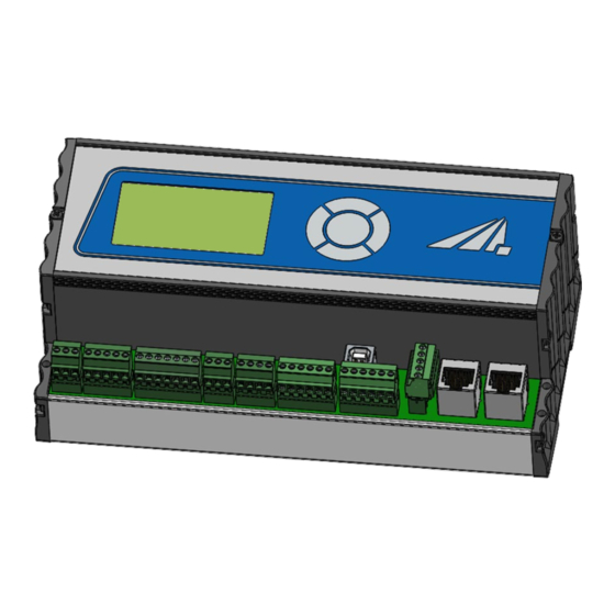
8 Commissioning Commissioning • Unpack all components and remove the packing materials. • Position the LED module at the desired position. Connect the UV LED module to the LedControl control unit, according to the enclosed • wiring diagram. LedControl DC (Image similar) For the operation of the system, the contact Enable/Enable (connector 5: pin 1 and 2 •... -
Page 26: Connection Example Of The Ledcontrol Dc
8 Commissioning WARNING Risk of injury By closing the enable/enable contact, the operator must ensure adequate protection of workers or other persons. Note that effective protective measures are necessary to comply with the exposure limits. By applying the enable signal, the operator confirms that all necessary protective measures to protect the operating personnel from direct and reflected UV radiation have been implemented and are effective. -
Page 27: Connection Example For Pl Kat 4
8 Commissioning The output power of the 24V auxiliary voltage required for the LedControl DC is 10 W. The necessary output power of the LED systems depends on the LED system and can be approx. 20 W to approx. 2000 W. The technical data for this can be found in the data sheets of the LED systems. -
Page 28: Operation
9 Operation Operation The LedControl is operated via five keys. These are located on the front panel to the right of the display. The keys and the function assignment are shown below: Function Up / LEDs on Down / LEDs off ... -
Page 29: Switch On
9 Operation 9.1 Switch on Switch on the control unit at the switch on the back. After starting the device, the logo first appears on the display followed by a short self-test. v xx.xx.xx During the self-test, the LED modules and the enable signal are checked and the status is displayed. -
Page 30: Led On / Off
9 Operation Powers and modes set in remotemode* are not transferred to "normal operation" and are not saved when the device is switched off. 9.3 LED On / Off When the LED is on, the status screen is displayed. Example: Power CH1: 50.0% CH2: 75.0%... -
Page 31: Change The Power
9 Operation Change the power Select the "Power 0..100%" menu item in the main menu. Power 100.0 % If your LEDControl is designed for several LED modules, select "all channels" or "single channel" in the submenu. All channels: The power can be set to the desired value using the or keys and . Confirm with OK () to return to the main menu. -
Page 32: Timer Mode / Irradiation Time
9 Operation With the key the channel can be switched off. With the key 100% is set. Settings below 2% and above 100% are reset to the limit values. Reset: All channels can be set to 0% or 100% simultaneously. With the single channel setting it is possible to set several LED modules to different powers. -
Page 33: Settings In The Main Menu
9 Operation If the "Irradiation time" menu item is not displayed, switch to the "Timer" operating mode. Irradiation time Time in [s] : 00 Here, the decimal place is selected with the or key and the time is set to the desired value with the ... - Page 34 9 Operation Settings Settings Trigger function Language Version Internal PWM/I.adj P-Monitoring In the settings menu and all submenus, use the and keys to select the active menu item. Use the key to confirm the selected menu item. Use to return to the previous menu. 9.7.1 Trigger function This menu item allows you to set the trigger function.
- Page 35 9 Operation 9.7.4 Internal No user settings are provided in this submenu. 9.7.5 PWM/I.adj* This submenu is used to switch between PWM control and I adjust, i.e. current control. 9.7.6 Power monitoring* Power monitoring is an option to measure the total power of the LED modules [in W]. In addition, an error will be output when the power falls below/exceeds the limit.
- Page 36 9 Operation In the submenu ''Tolerance'' you can set the tolerance of the power monitoring in percent. An error will be output when the power falls below/exceeds the tolerance. The error can be queried via programming interface*. The LEDs remain active even in the event of an error. There are two conditions for performance monitoring to check: Each channel must have a set power greater than 40%.
-
Page 37: Leveling - Level Multiple Led Segments
9 Operation 9.8 Leveling - Level multiple LED segments*. The Leveling option allows a head with several LED segments to control them centrally on the one hand and to align the individual LED segments with each other on the other. The leveling option is used for systems where leveling of the individual LED strands is possible or necessary. -
Page 38: Remote Operation - Programming Interface
10 Remote operation - programming interface * 10 Remote operation - programming interface * The LED system can be controlled via the programming interface* on the rear. Depending on the selected option, the connection is designed as USB, RS485 or RS232 connection. Operation via the programming interface is called remote and is visualized on the display. -
Page 39: Type Definition
10 Remote operation - programming interface * 10.2 Type definition BOOL: ASCII representation of the value: "1" = TRUE; "0" = FALSE • INT: ASCII representation of the value: 12345 • FLOAT: ASCII representation of the value: 1.2345E+01 • • STRING: ASCII representation of an alphanumeric string ARRAY[1..8] of .. -
Page 40: Command Overview
10 Remote operation - programming interface * 10.5 Command overview Usage Command Reply Value range Query serial number LSerialNo? LSerialNr: LedControl() (CRC) STRING Query type number LType? LType: LedControl() (CRC) STRING Firmware LFirmware? LFirmware: LedControl() (CRC) V00.00.00 - 99.99.99 query LAnzahlCH: # (CRC) Query number of LAnzahlCH? - Page 41 10 Remote operation - programming interface * HOLD = 0 Trigger&hold not active Electrical power LPowerCons? LPowerCons: (CRC) 0000-9999 [W] sensing head Query temperature LTemperature? LTemperature:\txx (CRC) 00-99 [°C] Query the number of internal channels LLevelCount? LLevelCount: X (CRC) X=number of channels (only with Leveling option)*.
-
Page 42: Checksum
10 Remote operation - programming interface * The adjustment of the power measurement and takes place only locally at the LedControl due to the active LEDs. The parameterization of the fan speeds and the overrun only takes place locally at the LedControl due to the heat dissipation. 10.6 Checksum All responses that are sent with data content must be provided with a checksum (CRC-16). -
Page 43: Initialization
10 Remote operation - programming interface * LAnzahlCH? LAnzahlCH: 40xCRC-16 LChPresent? LChPresent: 11110xCRC-16 LTriggerOnOff: LTriggerOnOff: 000xCRC-16 LSelect: 0110 !? LSelect: 01100xCRC-16 LPowerSet: 000. 0033. 7050. 1000.0 LPowerSet: 000. 0033. 7050. 1000. 00xCRC-16 LOnOff: LOnOff: 00x9908 LPowerSet? LPowerSet: 017. 2033. 7033. 7033.70x1CDE LChPresent? LChPresent: 11110x7BB3 LSerialNo? -
Page 44: Example Program For Starting The Ledcontrol
10 Remote operation - programming interface * LChPresent? LSelect! LPowerSet: ... LOnOff or LTriggerOnOff Only after the above commands the LED system is ready for operation and can be used. 10.8 Example program for starting the LEDControl Spaces are {TAB}. This example shows a Led Control with 5 channels. -
Page 45: Fehler / Error
11 Fehler / Error 11 Fehler / Error Error codes can be queried via the "LError?" command. Only the last error is displayed. Error confirmations always with NACK:No such command! The error code is then displayed in the error register. If a command is sent correctly, the error is cleared. -
Page 46: Software - Ledcontrol Remote For Programming Interface
12 Software - LedControl Remote for programming interface*. 12 Software - LedControl Remote for programming interface*. The "LedControl Remote" software is used for testing and controlling the LedControl control unit with the PC. The software enables: LED channels on and off •... - Page 47 12 Software - LedControl Remote for programming interface*. Listing of all COM ports located on the PC Opens an information window with: Software version number • Firmware • • Serial number Type number • Number of LED slots • For more information Equipment control The middle area of the software is used for Led Control control and monitoring.
-
Page 48: Install Software
12 Software - LedControl Remote for programming interface*. Errors and messages appear in the display for 3 s, errors are highlighted in red. The last ten messages are displayed here when the mouse pointer hovers over them. The left area is used to change settings The COM log area can be made invisible here by "COM log"... -
Page 49: Activate Led Channels
12 Software - LedControl Remote for programming interface*. If the LedControl is properly connected to the PC, the COM address appears at the top right. All COM ports on the PC are listed here. If several devices are connected, the correct address must be selected. -
Page 50: Switching Led Channels On And Off
12 Software - LedControl Remote for programming interface*. 12.4 Switching LED channels on and off One or more LED channels can be switched on or all channels can be switched off in the "Control" tab. The desired channels must be activated in the software and selected in the device. -
Page 51: Program Timer
12 Software - LedControl Remote for programming interface*. If more than one channel is activated, a master slider appears. The master slider can be changed by moving the slider, turning the mouse wheel or typing in the value. The intensity of the activated channels changes in percentage to the master. -
Page 52: Use And Manage Presets
12 Software - LedControl Remote for programming interface*. Start timer starts the timer. A loading bar appears which shows the progress of the timer. Cancel opens only when the timer is running and cancels it. 12.7 Use and manage presets To use or save a preset, the "Preset"... -
Page 53: Trigger Modes
12 Software - LedControl Remote for programming interface*. In the "Preset" window, the settings with which the preset is saved are displayed. Before clicking the Save button, the name of the preset must be set. The preset name may only be used once and must not contain a space, semicolon or line break. -
Page 54: Technical Data
13 Technical data 13 Technical data The pin assignment for special versions may differ and can be found in the "Technical Drawing" appendices. General data Ambient temperature +5 to 40 °C Storage temperature, approx. -10 to +60 °C Humidity 0% to 80% rel. humidity Body type, LedControl Top-hat rail mounting Mounting... -
Page 55: Interface Assignment
13 Technical data 13.1 Interface assignment The pin assignment is shown from left to right. Pin 1 is on the left. 1 Supply Plug 1 Signal Function Pin 1 +24 V Supply voltage Pin 2 Pin 3 Grounding Würth Elektronik WR-TBL Series 3633 - 3.81 mm 3pol Connection Order number: 691363310003 2 Communication to the Master*... - Page 56 13 Technical data 3 Trigger and status Plug 3 Signal Function Pin 1 Trigger IN 1 Trigger input (+24 V) Pin 2 Pin 3 Status OUT 1 Status output (+24 V) Pin 4 ERROR Low: ERROR (0 V) Pin 5 High: OK (+24 V) Pin 6 Reference mass...
- Page 57 13 Technical data 6 Head 1 Plug 6 Signal Function Pin 1 VCC1 Supply voltage 24 V Pin 2 Auxiliary voltage output Pin 3 +3V3 (3.3V, max 50 mA) Pin 4 PWM 1 PWM output signal Pin 5 Head1 Head detection Pin 6 Temp1 Temperature switch...
-
Page 58: Control
13 Technical data 9 Communication to slave Plug 9 Signal Function Pin 1 RX+* RS485/RS232 Pin 2 RX-* RS485 Pin 3 TX+* RS485/RS232 Pin 4 TX-* RS485 Pin 5 Reference mass Würth Elektronik WR-TBL Series 3633 - 3.81 mm 5pol Connection Order number: 691363310005 When using the RS232 interface option, only RX+ and TX+ are... - Page 59 13 Technical data +24V triggers a trigger. Continuous operation Depending on the trigger selection (Trigger or Trigger&Hold), the lamp is switched on when a trigger signal is detected or when it is permanently present. Timer operation In timer mode, external triggering is also possible.
-
Page 60: Led Module
13 Technical data 13.3 LED module LED module Type See nameplate Peak wavelength See nameplate Adjustable power 2 - 100% Dimensions LED module, approx. see drawing Dimensions, irradiation field, see drawing approx. Air cooling (Spot P and Series L) Cooling Water cooling (SFL), special versions: Passive cooling Risk group 3 according to DIN EN 62471:2009-... - Page 61 13 Technical data To prevent thermal overheating, sufficient ventilation must be ensured at all times. Take special care that the ventilation openings are not covered during operation. Cooling SFL The UV LED requires active water cooling. To prevent thermal overheating, sufficient cooling must be ensured at all times. Water inlet, pressure <...
-
Page 62: Spare Parts
14 Spare parts 14 Spare parts Contact for replacement orders: Opsytec Dr. Gröbel GmbH Am Hardtwald 6-8 76275 Ettlingen Germany Phone +49 - 7243 - 94 783 - 50 Visit us on the Internet: www.opsytec.de... -
Page 63: Transport, Storage And Disposal
15 Transport, storage and disposal 15 Transport, storage and disposal The conditions of the technical data apply to transport and storage. Storage is only permitted in closed rooms. The system must be protected against moisture or wetness. Do not expose the system to strong vibrations. -
Page 64: Error
16 Error 16 Error Error codes can be queried via the "LError?" command. Only the last error is displayed. Error confirmations always with NACK:No such command! The error code is then displayed in the error register. If a command is sent correctly, the error is cleared. general Error number Description... -
Page 65: Maintenance
17 Maintenance 17 Maintenance This chapter is aimed at qualified users with maintenance tasks. The LED system is largely maintenance-free. However, as light sources and LEDs have a limited service life, they must be replaced cyclically. We recommend changing the group of LED modules if the irradiance achieved •... -
Page 66: Declaration Of Conformity
18 Declaration of Conformity 18 Declaration of Conformity Manufacturer: Company name: Opsytec Dr. Gröbel GmbH Street: Am Hardtwald 6-8 Place: 76275 Ettlingen Country: Germany Authorized person for the compilation of technical Company name: Opsytec Dr. Gröbel GmbH documentation: Street: Am Hardtwald 6-8 Place: 76275 Ettlingen Country: Germany Product:... -
Page 67: Notes
19 NOTES 19 NOTES CAUTION THIS MANUAL CONTAINS IMPORTANT SAFETY INSTRUCTIONS. KEEP THESE INSTRUCTIONS IN A SAFE PLACE.
Need help?
Do you have a question about the UV LED LedControl DC and is the answer not in the manual?
Questions and answers