
Subscribe to Our Youtube Channel
Related Manuals for ESCO Technologies ETS-LINDGREN EMSense 10/40


Summary of Contents for ESCO Technologies ETS-LINDGREN EMSense 10/40
- Page 1 EMSense 10/40 Laser Powered Electric Field Probe With EMSense 10/40 Plug-In Card for EMCenter Product Manual...
-
Page 2: Copyright And Trademark
Copyright and Trademark ETS-Lindgren Inc. reserves the right to make changes to any products herein to improve functioning or design. Although the information in this document has been carefully reviewed and is believed to be reliable, ETS-Lindgren does not assume any liability arising out of the application or use of any product or circuit described herein;... -
Page 3: Safety Information
Safety Information High Voltage: Indicates presence of hazardous voltage. Unsafe practice could result in severe personal injury or death. Protective Earth Ground (Safety Ground): Indicates protective earth terminal. You should provide uninterruptible safety earth ground from the main power source to the product input wiring terminals, power cord, or supplied power cord set. -
Page 4: Notes, Cautions, And Warnings
Notes, Cautions, and Warnings Note: Denotes helpful information intended to provide tips for better use of the product. CAUTION: Denotes a hazard. Failure to follow instructions could result in minor personal injury and/or property damage. Included text gives proper procedures. WARNING: Denotes a hazard. -
Page 5: Table Of Contents
Table of Contents Copyright and Trademark ..................... 2 Revision Record ........................2 Safety Information ........................3 General Safety Considerations ....................3 Notes, Cautions, and Warnings .................... 4 Table of Contents ....................5 Introduction ......................7 Product Characteristics......................8 Related Products ........................9 ETS-Lindgren Product Information Bulletin ................. - Page 6 Handling Guidelines ......................38 Fiber Conditions ........................39 Service Procedures ......................39 Contacting ETS-Lindgren ..................... 39 Replacement and Optional Parts ..................39 Sending a Component for Service ..................40 Calibration Services and Annual Calibration ..............40 Upgrade Policies ........................40 Specifications ......................
-
Page 7: Introduction
Introduction The EMSense 10 electric field sensor is the most accurate ultra-wideband sensor designed for electric field strength measurements. The sensor is small and fully optically isolated to minimize field perturbation. EMSense 10 card EMSense 10 probe EMSense 40 probe Applications for the E-field sensor are: Radiated immunity field monitoring •... -
Page 8: Product Characteristics
Product Characteristics LASER Powered – The sensor is LASER powered without the need for batteries. This allows • 24/7 continuous testing at maximum performance without the need to change or recharge batteries. Superb Measurement Accuracy – To perform accurate field measurements, the E-field •... -
Page 9: Related Products
Related Products EMCenter System (2-Slot and 7-Slot) • The EMCenter is a modular EMC test system that serves as the user and computer interface for all the EMCenter plug-in cards and modules, such as the EMSense 10/40 field sensors. EMCenter units are available in 2-slot and 7- slot versions. -
Page 10: Emsense 10 Field Probe And Kits
EMSense 10 Field Probe and Kits The EMSense 10 sensor can be purchased as a stand-alone item or as part of a kit. EMSense 10 Field Probe Kits for Use with 2-Slot or 7-Slot EMCenter Note: Kits 1714963 and 1714964 do not include an EMCenter unit. The EMCenter 2-Slot or 7-Slot units are sold separately. - Page 11 EMSense 10 Field Probe Kits for Use with 1-Slot EMCenter Note: Kits 1714959 and 1714961 include an EMCenter 1 unit for connection to a PC. KIT 1714959 7007-201 10 M KIT, PROBE + CARD + EMCENTER 1 + 10 M FIBER CABLE 1710780 1702423 1703647...
-
Page 12: Emsense 40 Field Probe And Kits
EMSense 40 Field Probe and Kits The EMSense 40 sensor can be purchased as a stand-alone item or as part of a kit. Field Probe Kits for Use with 2-Slot or 7-Slot EMCenter Note: Kits 1741724 and 1741725 do not include an EMCenter unit. The EMCenter 2-Slot or 7-Slot units are sold separately. - Page 13 EMSense 40 Field Probe Kits for Use with 1-Slot EMCenter Note: Kits 1741726 and 1741727 include an EMCenter 1 unit for connection to a PC. KIT 1741726 7007-203 10 M KIT, PROBE + CARD + EMCENTER 1 + 10 M FIBER CABLE 1738260 1702423 1703647...
-
Page 14: Emsense 10/40 Individual Parts
EMSense 10/40 Individual Parts EMSense 10 E-field sensor (with fixed fiber cables): Electric field sensors to be used together with the plug-in card including small probe stand. Model: 7007-201 • Part Number: 1710780 • EMSense 40 E-field sensor (with fixed fiber cables): Electric field sensors to be used together with the plug-in card including small probe stand. -
Page 15: Fiber Optic Cables
Fiber Optic Cables Use an extension fiber to connect the sensor to the plug-in card mounted in the EMCenter. This extension fiber is a duplex fiber cable and uses dissimilar connectors to avoid incorrect connections. The fiber optic cable with FC connectors feeds LASER light to the field sensor. The fiber optic cable with ST connectors is used for bi-directional data communication between the field sensor and the plug-in card. -
Page 16: Processor Requirement
Processor Requirement Note: The 2-slot and 7-slot EMCenter require an ARM processor board with firmware version 3.3.3 or higher to operate the EMSense 10/40 field probes and interface card. 2-slot and 7-slot EMCenter systems utilizing an X86 processor board and/or firmware version 3.3.0 or older are not supported and will not communicate with the EMSense interface card. -
Page 17: Operation
Operation Installation CAUTION: Before connecting any components, follow the safety information in the ETS-Lindgren Product Information Bulletin included with your shipment. WARNING: Always unplug the unit before starting maintenance to prevent electrical shock. Maintenance includes removal of the plug-in cards or the top panel. - Page 18 6. Plug the interlock into the connector on the back of the EMCenter. 7. Connect the plug-in card to the desired device(s). Place the EMSense 10 E-field sensor where the field strength is to be measured. Clean the ends of the fibers and connect the cables to both the sensor and the plug-in card.
-
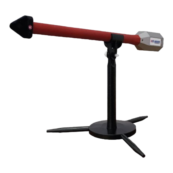
Page 19: Probe Stand
Probe Stand The EMSense 10 is supplied with a probe stand consisting of the following parts: a base, the feet (in three pcs), a pole, and an angle mount. The probe stand parts can be easily assembled together. The 3 feet can be screwed into the side of the base. -
Page 20: Laser Safety
The use of the mounting angle is optional. For isotropic measurements of an electrical field of which the polarization is unknown (for example in reverb chamber / mode-stir chambers) the mounting angle is not needed, see left picture. For accurate measurements of electrical field with a known polarization, the mounting angle can be used to position one axis of the EMSense 10 parallel to the field. -
Page 21: Safety Precautions
Safety Precautions LASER RADIATION AVOID EXPOSURE TO BEAM CLASS 3B LASER PRODUCT WAVELENGTH 808 nm OPTICAL POWER 0.5 W CAUTION: Never look into any of the fiber optic connectors. The laser emits an infrared beam that is invisible to the naked eye. •... -
Page 22: Activate Laser Code
To make the EMCenter as safe as possible, the primary safety system of each plug-in card is designed to work standalone, without any intervention from the EMCenter. Apart from this, the EMCenter has its own safety interlock system, which is connected in series with the interlock system of every installed card. - Page 23 If the activation process is interrupted (and released ‘Start’ button by accident), • the laser will not be activated. • The user is warned by an audible warning when the start button is pressed by accident (i.e. without the intention to activate the laser). To prevent accidental activation of the laser, an auditory warning will alert you of •...
- Page 24 Precaution for 2-slot and 7-slot EMCenter As a safety precaution, products that use a LASER can only be turned on using a LASER Code. This code can be entered into the system by use of the touchscreen of the EMCenter. (This safety feature is linked to the EMCenter 2-slot and 7-slot version.
- Page 25 To change the laser code, the user will be asked to enter the current code once and the new code twice (for confirmation). Press ‘Close’ to leave each notification and enter the code in the following numeric window. The probe stand parts can be easily assembled together. The 3 feet can be screwed into the side of the base.
-
Page 26: Manual Control
Manual Control Back Panel The following connections and indicators are found at the back panel of the plug-in card: Fiber Optic Cables Use an extension fiber to connect the sensor to the plug-in card mounted in the EMCenter. This extension fiber is a duplex fiber cable and uses dissimilar connectors to avoid incorrect connections. -
Page 27: Touchscreen
Touchscreen Home Screen Readings from the probe can be taken directly from the 2-slot or 7-slot EMCenter screen. The status box tells you the Etot value in V/m. The ‘STATUS’ box in the main screen of the EMCenter only displays the total isotropic field strength. - Page 28 Starting the LASER Powered Sensor The LASER of the EMSense 10 field sensor can be started from the ‘main’ window of the EMCenter. To activate the sensor, press the ‘Start’ button for the required sensor and, within 4 seconds, the ‘ACK’ button. A short sound will be audible until the safety loop is closed successfully.
- Page 29 Zeroing the Probe The ‘STATUS’ box will now indicate “Press this button to zero” and after pressing this button the zeroing of the probe will be started. As soon as the probe is zeroed, the ‘STATUS’ box will display the measured field strength of the probe.
- Page 30 EMControl Instrument Screen This page shows the Probe Configuration and Advanced Measurement Data of the EMSense 10 probe. The ‘‘Instrument’-screen will display the field strength in a large font, together with the field strength data of each separate axis. In addition; probe information and LASER information are also displayed in the ‘Instrument’-screen.
- Page 31 • Pressing the ‘Zero’ button will arrange that the EMSense 10 sensor reading will be ‘zero-ed’. Note: Ensure the amplifier is turned off prior to zeroing the field probe. ets-lindgren.com EMSense 10 & 40 User Manual | 31 of 46...
-
Page 32: Emsense 10 Typical Performance Data
User Correction Data Every new EMSense 10 probe is factory adjusted and verified. All required correction data is stored inside the field probe. The EMSense 10 probe has the feature to store external calibration data as “user correction factors” inside the probe. This means that the correction data will be automatically applied to the measured field in run time at the specified frequency. -
Page 33: Typical Probe Isotropic Response At 1000 Mhz
Typical Probe Isotropic Response at 1000 MHz Typical Probe Isotropic Response at 3000 MHz ets-lindgren.com EMSense 10 & 40 User Manual | 33 of 46... -
Page 34: Typical Probe Isotropic Response At 6000 Mhz
Typical Probe Isotropic Response at 6000 MHz Remote Control To use the EMSense 10/40 remote commands, read the manual document 399342 EMCenter for examples and a full command list. ets-lindgren.com EMSense 10 & 40 User Manual | 34 of 46... -
Page 35: Software Configuration For Emcenter 1-Slot
Software Configuration for EMCenter 1-slot To control the EMSense 10 from a computer, custom-made software can be used. ProbeView V is a simple software package available for download at ETS-Lindgren.com that provides real-time display, logging, and analysis of probe data as a support tool for EMF measurements. - Page 36 ProbeView V Setup If you already have a version of ProbeView on your PC, uninstall it before installing ProbeView V. 1. Download and install ProbeView V.msi. 2. Accept all the license agreements and select FINISH. 3. Connect the fiber optic cable from the fiber optic ports on the probe to the EMSense 10 in the EMCenter and then connect the EMCenter to the PC.
-
Page 37: Maintenance
Maintenance CAUTION: Before performing any maintenance, follow the safety information in the ETS-Lindgren Product Information Bulletin included with your shipment. WARNING: Maintenance of the EMCenter is limited to external components such as cables or connectors. If you have any questions concerning maintenance, contact ETS-Lindgren Customer Service. -
Page 38: Fiber Optic Maintenance
Fiber Optic Maintenance The fiber optic cables in the EMSense 10/40 are a crucial part of the system. Fiber optic connectors and cables can be damaged from airborne particles, humidity and moisture, oils from the human body, and debris from the connectors they plug into. Always handle connectors and cables with care, using the following guidelines. -
Page 39: Fiber Conditions
Fiber Conditions Use the examples and instructions in the following figure as a guideline for further fiber maintenance. If you have doubts about the condition of the fiber optic cables, please contact your local reseller or ETS-Lindgren for assistance and/or advice. Service Procedures Contacting ETS-Lindgren Note: Please see... -
Page 40: Sending A Component For Service
Sending a Component for Service For the steps to return a system or system component to ETS-Lindgren for service, see the Product Information Bulletin included with your shipment. Calibration Services and Annual Calibration See the Product Information Bulletin included with your shipment for information on ETS-Lindgren calibration services. -
Page 41: Specifications
Specifications EMSense 10 Probe Specifications Electrical (EMSense 10) Field measurement 1 to 750 V/m range Max input level 1000 V/m before damage Frequency range 10 kHz to 10 GHz (usable to 12 GHz) Frequency response ± 1 dB 10 kHz to 10 GHz (with internal correction) Resolution... -
Page 42: Physical (Emsense 10)
Physical (EMSense 10) Shape of housing Spherical Diameter of housing 0.98 in (2.5 cm) Weight 1.77 oz (65 g) Electrical 6.9 in (117 cm dimensions Temperature range 32° F to 104° F (operating) (0° C to 40° C) Relative humidity 10% –... -
Page 43: Calibration (Emsense 10)
Calibration (EMSense 10) Factory accredited Internally stored, ISO17025 calibration calibration EMSense 40 Probe Specifications Electrical (EMSense 40) Field measurement 2 to 1000 V/m range Max input level 2000 V/m before damage Frequency range 10 MHz to 40 GHz Frequency response ±... -
Page 44: Physical (Emsense 40)
Physical (EMSense 40) Shape of housing Stalk probe Diameter of housing 0.57 in (1.5 cm) Weight 3.2 oz (91 g) Electrical 6.9 in (117 cm dimensions Temperature range 32° F to 104° F (operating) (0° C to 40° C) Relative humidity 10% –... -
Page 45: Calibration (Emsense 40)
LASER switch off < 10 ms time Calibration (EMSense 40) Factory accredited Internally stored, ISO17025 calibration calibration ets-lindgren.com EMSense 10 & 40 User Manual | 45 of 46... -
Page 46: Appendix A: Ec Declaration On Conformity
Appendix A: EC Declaration on Conformity ETS-Lindgren Inc. declares these products to be in conformity with the following standards and provisions: Product EMSense 10/40 Electric Field Probes Models: Directives: EMC Directive 2014/30/EU Low Voltage Directive 2014/35/EU RoHS Directive: 2015/863/EU Emission: EN 61326-1:2013, Class A1 Electrical equipment for measurement, control and laboratory use.
Need help?
Do you have a question about the ETS-LINDGREN EMSense 10/40 and is the answer not in the manual?
Questions and answers