Table of Contents
Advertisement
Quick Links
Advertisement
Table of Contents

Related Manuals for GreenValley LiGrip O1 Lite


Summary of Contents for GreenValley LiGrip O1 Lite
- Page 1 LiGrip O1 Lite Lightweight 3D Laser Scanner Quick Start Manual Version A.00...
-
Page 3: Table Of Contents
Contents I. Product Structure II. Device Installation and Removal III. Power On IV. Registration and Activation V. Data Collection Status Light Indicators and Interpretations VI. RTK Light Status Indicators and Interpretations VII. Connecting the Device Using the APP Ⅷ . Choosing the Initialization Location IX. -
Page 4: Product Structure
I. Product Structure 1. LiDAR sensor 2. RTK Module Mounting Holes (4 in total) 3. Indicator Lights (Left: Power indicator light , Right: Data acquisition status indicator light) 4. Power Button 5. Data Collection Button 6. Type-C Port and TF Card Slot 7. -
Page 5: Device Installation And Removal
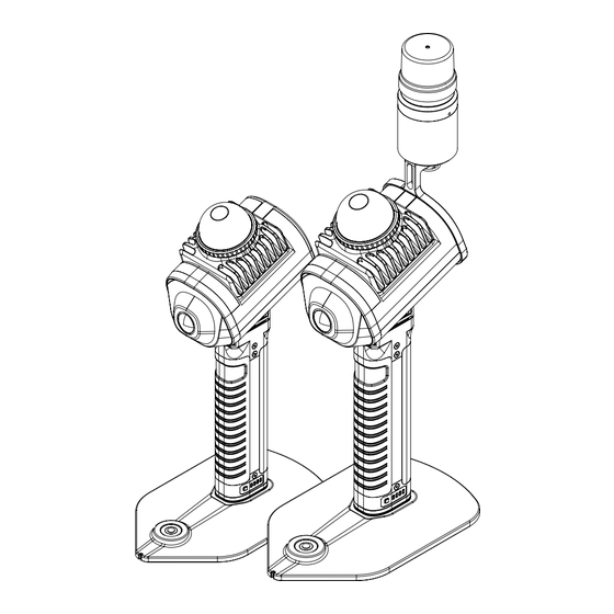
II. Device Installation and Removal 2.1 Battery Installation and Removal 2.1.1 Installation Align the battery with the bottom of the device, gently insert it until you hear a click, then press down the locking handle. 2.1.2 Removal To remove the device, flip open the locking handle, press the anti-detachment button, and pull the battery out towards you. - Page 6 2.2 Base Stand Installation and Removal 2.2.1 Installation Align the mounting holes of the base stand with the holes at the bottom of the battery, then tighten the base stand screws. 2.2.2 Removal Unscrew the base stand screws and pull out the base stand. 2.3 RTK Module Installation and Removal 2.3.1 Installation (1)Preparing the RTK Bracket, M2.5*4 Screws,Screwdriver, RTK Module, SIM card pin ,LEMO...
- Page 7 (3) The RTK bracket is mounted on the back of the device. Use the screwdriver to tighten the screws. (4) Align the bottom of the RTK module with the limiting holes at the top of the RTK bracket and tighten the RTK fixing knob. ©2024 Map The World In 3D...
-
Page 8: Power On
(5) Connect the RTK module to the device's main unit with the LEMO cable. 2.3.2 Removal For general operations, only the RTK module needs to be removed; the mounting bracket can remain attached. To remove the RTK module, first disconnect the LEMO cable from the RTK module. Then, loosen the RTK fixing knob and remove the RTK module. -
Page 9: Registration And Activation
After the device is turned on, turn on the cell phone WIFI, search for the corresponding WIFI of the device and connect it. Device WiFi: LiGrip O1 Lite-**** (last four digits of SN) Password: greenvalley ©2024 Map The World In 3D... - Page 10 (2) Open the APP and connect to device (3) Activate the device After connecting the device, APP pops up the interface that needs to be activated. According to the APP prompts, complete the switching of the network and finally complete the activation. activation screen Prompt to switch WIFI, click OK Disconnect the device WIFI...
- Page 11 Upload activation code, OK Connect the device WIFI activating After the APP prompts for successful activation, connect to device,and finally restart the device ©2024 Map The World In 3D...
-
Page 12: Data Collection Status Light Indicators And Interpretations
If APP operation is not required, this step can be skipped. Open the GreenValley APP, and connect your mobile device (phone/tablet) to the O1 Lite WiFi. Select the '+' sign at the top right corner of the APP, click on "LiGrip", then click on the name of the device you have purchased. -
Page 13: Ⅷ . Choosing The Initialization Location
Device WiFi: LiGrip O1 Lite-**** (last four digits of SN) Password: greenvalley Ⅷ . Choosing the Initialization Location The so-called initialization location refers to a location that meets the prerequisites for the device to run the initialization program correctly and achieve optimal results. -
Page 14: Starting Data Collection
8.2 Operating without the RTK Module (1)Place the device on stable ground or a platform. For indoor operations, place the device on the floor. (2)Avoid initializing in doorways or areas with high pedestrian/vehicle traffic. (3)Avoid initializing in empty areas, such as squares or sports fields. (4)When initializing in a mine, position the device in the direction of the mine's progression. - Page 15 Once RTK configuration is successful, it is not necessary to reconfigure upon next startup; the system will automatically use the previous configuration parameters for automatic configuration. 9.2 Collecting Data Using the APP 9.2.1 Operating with RTK (1) New Acquisition There are two methods to create a new acquisition. Tap "Start Collection,"...
- Page 16 ©2024 Map The World In 3D...
- Page 17 Task details such as task name, scene, weather, temperature, and photos from the field can be entered. All options are optional except for the task name; Note: 1. You can choose whether to save real-time Pointcloud in the task interface. By default, it is closed and real-time results will not be saved 2.
- Page 18 Note: During the collection process, if the APP interface prompts "The current SD card speed is too low. Do you want to stop collecting??," it is recommended to stop collecting, backup the data, and format the SD card before proceeding. (4)...
- Page 19 9.2.2 Operation with PPK Absolute positioning calculations are performed using PPK(you need to set up your own base station.), thus, unlike operations with RTK, there is no need to monitor for a real-time fixed solution during collection. All other steps are identical to those during operations with RTK. 9.2.3 Operation without a RTK Module When operating without a RTK module, if absolute coordinate results are required, then the GCP base stand will be required.
- Page 20 Tap the GCP collection button on the APP's screen (you can rename the GCP; by default, it's LiGrip *, where * is a number that automatically increments with each collection). At this moment, the device's status light will flash fast. Note: Please remain still during GCP collection The collection is completed when the APP signals the end of the process, or the status light starts flashing slowly.
-
Page 21: Data Transfer
(5)Ending Data Collection The procedure for ending data collection is consistent with operations involving RTK. 9.3 Button-Based Data Collection When opting for button-based data collection, without the APP's prompts or status displays, it becomes essential to closely observe the device's status lights (as described in sections V and VI) and strictly adhere to the initialization location selection guidelines set forth in section Ⅷ... - Page 22 image_time.bin IMG folder pic_*.bin .LAZ Real-time RealTimeResult processing results Subfolder A folder .xyz Real-time trajecton .bag fie Subfolder B .log Project folder GNSS Raw Data Subfolder C .rtk Subtask name and RTK positioning Project name results Details of collection mission.json tasks Attribute information .gvlog...
-
Page 23: Device Shutdown
10.2 Copying via Type-C Connect a USB drive or portable hard disk to the device's Type-C port. Use the GreenValley APP to connect to WiFi, select one or more projects from the project list, and copy the selected project(s) to the USB drive. Wait until "Project Copy Successful" is displayed before removing the drive. -
Page 24: Slam Process
XII. SLAM Process Use the latest version of LiDAR 360 MLS, version 7.2 or above, for SLAM processing. Refer to the LiDAR 360 MLS software manual for hardware requirements. 12.1 Processing Data with RTK 1. Click on the MLS interface to create a new SLAM project, or go to File -New -Create New SLAM Project". - Page 25 4.Do not select a coordinate system; proceed directly to the next step. 5.Configure the project folder and project file name, leaving them as default, and click finish. ©2024 Map The World In 3D...
- Page 26 6.After entering the main interface, click the start button Note: If there is a need to modify settings, you can do so within the project settings. For detailed instructions, please refer to the LiDAR 360 MLS software operation manual. Wait for the program to complete running to obtain the final point cloud data results. 12.2 Processing PPK Data Before processing PPK data, it's necessary to prepare base station data (usually in RINEX format).
- Page 27 (3) For coordinate system configuration, select the target coordinate system. You can quickly find a coordinate system by using the "Filter" to input keywords, then proceed to the next step. Finally, configure the project save location and name. ©2024 Map The World In 3D...
- Page 28 (4) After entering the main interface, click the start button. The program will first run PPK, then proceed with the SLAM process. 12.3 SLAM process with Relative Coordinates This process is consistent with 12.1, except there is no need to configure GNSS data and the coordinate system.
- Page 29 3.In the ASCII file dialog box, simply click "Apply . This will display the locations of the collected points on the interface. 4. In the point pairs registration interface, click on "Load Reference Points. ©2024 Map The World In 3D...
- Page 30 Set up the columns corresponding to X and Y, noting that X corresponds to easting and Y to northing. Click "Apply. 5.Click on " Apply GCP Transformation. The final point cloud result will now align with the coordinates of the control points. ©2024 Map The World In 3D...
-
Page 31: Batch Processing
6.If the GCP conversion is not satisfactory, or if the control points have been entered incorrectly, you can click the restore button to point the cloud to its original state XIII. Batch Processing From the MLS main interface, click on "Batch Processing," or go to "File" -> "New" -> "Batch Processing . - Page 32 If you have any questions or suggestions about the manual, please contact us through the following methods: E-mail:info@greenvalleyintl.com Address:729 Heinz Avenue, Space 9, Berkeley, California 94710, U.S.A Map The World In 3D www.greenvalleyintl.com...
Need help?
Do you have a question about the LiGrip O1 Lite and is the answer not in the manual?
Questions and answers