in.hub HUB-VM102 Instruction Manual
Vibration monitoring
Hide thumbs
Also See for HUB-VM102:
- Operating instructions manual (27 pages) ,
- Programming manual (23 pages)

Related Manuals for in.hub HUB-VM102


Summary of Contents for in.hub HUB-VM102
- Page 1 INSTRUCTION MANUAL Vibration monitoring HUB-VM102 Document version 1.1 Release date 2024-04-22...
-
Page 2: Table Of Contents
Assembly ..........................13 Mounting as a single device ........................13 Mounting on the backplane bus ........................ 14 Dismounting ..............................14 Commissioning ........................15 Interfaces of the HUB-VM102 ........................15 5.1.1 LED display ............................15 5.1.2 Ethernet (ETH) ..........................15 5.1.3 CH1 and CH2 ............................. -
Page 3: Legal Information
Legal information 1 Legal information Warning concept This manual contains instructions that you must observe for your personal safety and to prevent damage to property. Depending on the hazard level, the warnings are presented in descending order as follows: DANGER Indicates a direct hazard for humans. - Page 4 If third-party products and components are used, they must be recommended or approved by in.hub. Proper storage, installation, commissioning, and operation are essential for the correct and safe operation of the product.
-
Page 5: General Information
User Manual for the SIINEOS system software • Instruction Manual for the respective master gateway (HUB-GM100 or HUB-GM200) 2.3 Open source A list of the open-source software used for the HUB-VM102 can be found in the in.hub download portal at https://download.inhub.de/vm102. 2.4 General instructions for use in.hub... -
Page 6: Safety Requirements
General information 2.6 Safety requirements The product should be handled in accordance with the following DIN standards: • DIN EN 61340-5-1:2017-07 Electrostatics - Part 5-1: Protection of electronic components against electrostatic phenomena - General requirements • DIN EN 61010-1:2020-03 Safety requirements for electrical equipment for measurement, control and laboratory use - Part 1: General requirements •... -
Page 7: Product Information
Product information 3 Product information The HUB-VM102 module is specially designed for the detection of up to 2 parallel vibration signals. It is also possible to limit the measured frequency range using various digital filters. At the same time, the ADC instantaneous values can be temporarily stored in the internal RAM. -
Page 8: Use Cases
Product information Use cases The HUB-VM102 is ideal for: • Long-term monitoring of conditions, generators, motors, gearboxes, turbines, pumps, fans, compressors, machines, bearings • Vibration and impact testing, quality assurance and product testing Special features • Continuous measurement of effective value (RMS) and peak value •... -
Page 9: Hardware - Structure And Interfaces
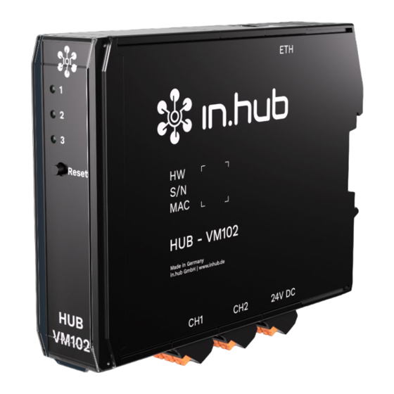
Product information 3.2 Hardware - Structure and interfaces Fig. 2: Side views and front view of the HUB-VM102 incl. interfaces Device-specific information that can be read with a QR code scanner HW: Hardware revision number S/N: in.hub-internal serial number MAC: Hardware address of the Ethernet network adapter... -
Page 10: Led Display
Clamping device for DIN rail installation 3.3 LED display The three LEDs on the front of the device indicate the following states: Fig. 3: LED status display on the front panel of the HUB-VM102 Device status Operating status of the IEPE interface 1 Operating status of the IEPE interface 2 3.3.1... -
Page 11: Led 2 & 3: Operating Status Of The Iepe Interface 1 And 2
Product information 3.3.2 LED 2 & 3: Operating status of the IEPE interface 1 and 2 LED behavior Color Meaning Permanent light Green Sensor ready for operation Permanent light No sensor connected, defective sensor or cable (short circuit or open) 3.3.3 LED on the ETH socket The LEDs can only be seen from above. -
Page 12: Assembly
Assembly 4 Assembly The HUB-VM102 is designed for mounting on a DIN rail complient with DIN EN 60715 (35 mm). Observe the applicable safety and accident prevention regulations for specific areas of application, e.g. the Machinery Directive. • Always switch the power supply off. -
Page 13: Mounting On The Backplane Bus
3. Check that the connector is also attached to the master gateway or the previous module to which you want to connect the HUB-VM102. 4. Click the HUB-VM102 onto the DIN rail and slide it up to the gateway or module so that the pins of the two backplane bus connectors interlock. -
Page 14: Commissioning
Commissioning 5 Commissioning Interfaces of the HUB-VM102 The following chapter provides an overview of the interfaces of the HUB-VM102 and provides the information you need to connect these interfaces. 5.1.1 LED display • 3 x LED (red/green) on the front panel •... -
Page 15: Power Supply
Commissioning Specification digital input • EN61131-2 Type1/3 conform • Switching threshold adjustable between 1...12 V, 0.5 V hysteresis • Pull-down current ~2 mA • Bandwidth = 10 kHz • Input resistance = 1 MOhm, max. 30 V • Dielectric strength according to EN61131-2 30V Specification analog input •... -
Page 16: Establishing Own Power Supply
Commissioning 5.2 Establishing own power supply The HUB-VM102 requires its own power supply if it is NOT connected via the backplane bus of the master gateway. As soon as the HUB-VM102 is installed separately from the master gateway, you must supply it with power separately. -
Page 17: Further Steps In Siineos Of The Master Gateway
Further steps in SIINEOS of the master gateway 6 Further steps in SIINEOS of the master gateway Now switch to the master gateway and log in to SIINEOS to create the HUB-VM102 as an I/O unit. All steps required for working in SIINEOS and for configuring the interfaces, data pre- processing and displaying measured values are described in detail in the SIINEOS user manual. -
Page 18: Technical Data
Technical data 7 Technical data Data Values Voltage range of the power 24 V DC ± 10 % | reverse polarity protected and overload supply protected Power consumption ~130 mA Microcontroller 166 MHz, 32 Bit ARM Cortex M7 Memory Flash: Dualflash, 2 x 512 kB Internal RAM: 358 kB + 128 kB fast RAM External RAM: maximum available memory = 16 MB Interfaces... - Page 19 Technical data Fig. 8: Schematic drawing of the HUB-VM102 (dimensions in mm)
-
Page 20: Eu Declaration Of Conformity
EU Declaration of Conformity 8 EU Declaration of Conformity... - Page 21 EU Declaration of Conformity...
- Page 22 EU Declaration of Conformity...
Need help?
Do you have a question about the HUB-VM102 and is the answer not in the manual?
Questions and answers