Table of Contents
Advertisement
Available languages
Available languages
Quick Links
SISTEMAS VRV UNIDAD EXTERIOR
VRF SYSTEM OUTDOOR UNIT
SYSTÈME VRV UNITÉ EXTÉRIEURE
SISTEMA VRV UNIDADE EXTERIOR
SERIE JR8-R32
MANUAL
DE INSTRUCCIONES
INSTRUCTION MANUAL
GUIDE D´UTILISATION
MANUAL DE INSTRUÇÕES
Escanee para ver este manual en otros idiomas y actualizaciones
Scan for manual in other languages and further updates
Manuel dans d'autres langues et mis à jour
V.1
Manual em outras línguas e actualizações
Advertisement
Chapters
Table of Contents
Troubleshooting

Related Manuals for Johnson JR8-R32 Series


Summary of Contents for Johnson JR8-R32 Series
- Page 1 SISTEMAS VRV UNIDAD EXTERIOR VRF SYSTEM OUTDOOR UNIT SYSTÈME VRV UNITÉ EXTÉRIEURE SISTEMA VRV UNIDADE EXTERIOR SERIE JR8-R32 MANUAL DE INSTRUCCIONES INSTRUCTION MANUAL GUIDE D´UTILISATION MANUAL DE INSTRUÇÕES Escanee para ver este manual en otros idiomas y actualizaciones Scan for manual in other languages and further updates Manuel dans d'autres langues et mis à...
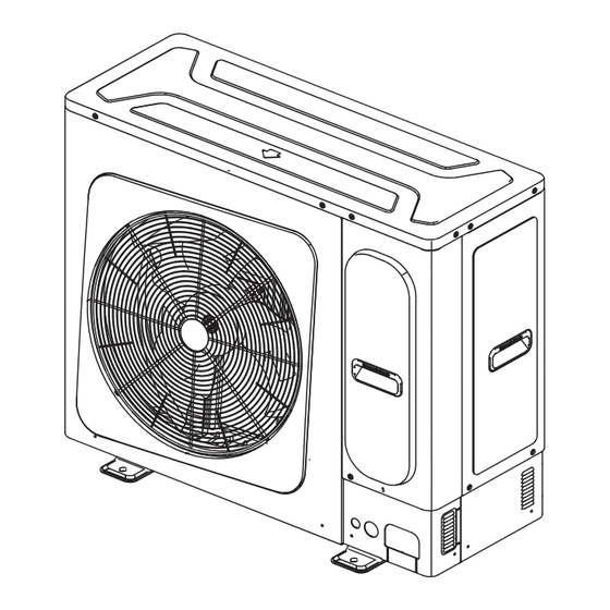
- Page 2 Entrada de aire Salida de aire Soporte de montaje Conector de la tubería del refrigerante NOTA Las figuras que aparecen en este manual son sólo a modo de explicación. Pueden ser ligeramente diferentes a las del equipo de aire acondicionado que ha adquirido (según el modelo). La forma real prevalecerá Las unidades cumplen con la norma IEC 61000-3-12.
- Page 3 Tabla 1 Amin(m Mmax(kg)--(a)/(b)/(c) Amin(m Mmax(kg)--(a)/(b)/(c) Amin(m Mmax(kg)--(a)/(b)/(c) 0.682/2.048/2.503 2.315/6.946/7.7 3.202/7.7/7.7 0.763/2.29/2.798 2.34/7.021/7.7 3.22/7.7/7.7 0.836/2.508/3.066 2.365/7.095/7.7 3.238/7.7/7.7 0.903/2.709/3.311 2.389/7.169/7.7 3.256/7.7/7.7 0.965/2.896/3.54 2.413/7.241/7.7 3.274/7.7/7.7 1.024/3.072/3.755 2.437/7.313/7.7 3.292/7.7/7.7 1.079/3.238/3.958 2.461/7.385/7.7 3.309/7.7/7.7 1.132/3.396/4.151 2.485/7.455/7.7 3.327/7.7/7.7 1.182/3.547/4.336 2.508/7.525/7.7 3.344/7.7/7.7 1.23/3.692/4.513 2.531/7.595/7.7 3.362/7.7/7.7 1.277/3.832/4.683 2.554/7.664/7.7 3.379/7.7/7.7 1.322/3.966/4.847 2.577/7.7/7.7...
-
Page 4: Table Of Contents
ÍNDICE 1 Sobre la documentación 2 Símbolos de seguridad Explicación de los símbolos de seguridad Explicación de los símbolos mostrados Sobre el refrigerante Manual de funcionamiento 3 Información importante para el usuario 4 Información del sistema Disposición del sistema 5 Instrucciones de funcionamiento Rango de funcionamiento Sistema de funcionamiento Programa de deshumidificación... - Page 5 14 Instalación de la tubería de refrigerante 14.1 Selección y preparación de las tuberías de refrigerante Conexión de las tuberías 14.2 Comprobaciones de las tuberías 14.3 15 Carga de refrigerante 15.1 Calcular la carga adicional de refrigerante 16 Cableado eléctrico 16.1 Requisitos del dispositivo de seguridad Cableado de comunicación...
-
Page 6: Sobre La Documentación
1 Sobre la documentación ATENCIÓN NOTA Indica un riesgo de nivel bajo que, de no evitarse, puede resultar en lesiones leves o moderadas. Asegúrese de que el usuario tiene la documentación impresa y pídale que la guarde para futura referencia. NOTA Público objetivo Una situación que puede causar daños al... -
Page 7: Manual De Funcionamiento
PELIGRO Para la instalación de la unidad interior, consulte el manual de instalación y funcionamiento correspondiente. Las instrucciones están dirigidas exclusivamente Si la unidad interior se instala en un área sin a montadores e instaladores autorizados: ventilación, dicha área deberá estar construida de tal ●... - Page 8 2.3.2 Limitaciones de la sala de instalación Además, la carga máxima de refrigerante también está relacionada con la altura de instalación del kit ACS y El sistema utiliza el refrigerante R32, que está clasificado módulo hidráulico unidad interior. como clase A2 y es inflamable según la norma EN 60335-2-40.
- Page 9 3. Información de seguridad importante ADVERTENCIA • Antes de comenzar a trabajar en sistemas que ADVERTENCIA contienen refrigerantes inflamables, necesarios los controles de seguridad para • Este aparato puede ser utilizado por niños de 8 minimizar el riesgo de ignición años en adelante y personas con capacidades físicas, sensoriales o mentales disminuidas o con •...
- Page 10 – La tubería de refrigeración o sus componentes se • Verifique que el cableado no sea objeto de instalan en una posición en la que sea improbable efectos como el desgaste, la corrosión, la que estén expuestos a cualquier sustancia que pueda presión excesiva, las vibraciones, unos extremos corroer los componentes que contienen refrigerante, afilados o cualquier otro efecto medioambiental...
- Page 11 • Al retirar el refrigerante de un sistema, ya sea • Asegúrese produzca para su mantenimiento o desmantelamiento, se contaminación diferentes refrigerantes recomienda extraer todos los refrigerantes de cuando utilice un equipo de carga. Las forma segura. mangueras o las tuberías deben ser lo más cortas posible para minimizar la cantidad de •...
- Page 12 ADVERTENCIA Para evitar lesiones, no retire la protección del ventilador de la unidad exterior. No toque la salida del aire ni las palas horizontales cuando están en funcionamiento. No utilice el aire acondicionado con las manos Sus dedos pueden quedar atrapados o la unidad mojadas.
-
Page 13: Información Del Sistema
Caso 3: ODU conectada a IDU VRV y módulo hidráulico La temperatura del circuito refrigerante será elevada. Mantenga cable interconexión alejado del tubo de cobre. El nivel de presión acústica es inferior a 70 dB(A). Este aparato está destinado a ser utilizado por usuarios expertos o formados en las tiendas, en la industria ligera y en las granjas, o para uso comercial por parte de... -
Page 14: Instrucciones De Funcionamiento
5.2 Sistema de funcionamiento 5 Instrucciones de funcionamiento 5.2.1 Funcionamiento del sistema El programa operativo varía con las diferentes combina- 5.1 Rango de funcionamiento ciones de la unidad exterior y del controlador. Para proteger esta unidad, conecte la fuente de alimen- Utilice el sistema con las siguientes temperaturas para tación principal 12 horas antes de empezar a utilizarla. -
Page 15: Programa De Deshumidificación
5.2.3 Funcionamiento de la calefacción 5.2.5 Uso del sistema En comparación con la operación de refrigeración, la Pulse el botón de selección de modo de la interfaz operación de calefacción lleva más tiempo. de usuario para elegir el modo de funcionamiento: Realice las siguientes operaciones para evitar que la AUTO capacidad de calefacción disminuya o para evitar que salga... -
Page 16: Mantenimiento Yreparación
Calefacción ADVERTENCIA Hay mucho polvo y residuos en el filtro de la IDU. • No intente modificar, desmontar, retirar, reinstalar La salida de aire de la IDU está bloqueada. o reparar esta unidad, ya que el desmontaje o la instalación incorrecta de la unidad puede provocar una descarga eléctrica o un incendio. -
Page 17: Solución De Problemas
6.2.3.2 Mantenimiento después de que la ADVERTENCIA unidad esté parada mucho tiempo Por ejemplo, a principios de verano o de invierno. Si el disyuntor se rompe, no utilice ningún disyuntor no especificado u otro cable para Revise y retire todos los objetos que puedan obstruir sustituir el disyuntor original. - Page 18 Tabla 7-1 Síntomas Causas Solución • Espere a que la alimentación se • Fallo de alimentación. restablezca. • El disyuntor está apagado. La unidad no se pone en marcha • Conecte la alimentación. • Las pilas del mando a distancia están •...
-
Page 19: Cambio Del Lugar De Instalación
7.3 Síntomas de fallo: Problemas Síntoma 6: las unidades emiten olores no relacionados con el aparato La unidad puede absorber el olor de las habitaciones, los muebles, los cigarrillos, etc. y volver a emitirlo. Síntoma 1: el sistema no funciona Síntoma 7: el ventilador de la unidad exterior no gira. - Page 20 Warning Si se producen fugas de gas refrigerante durante la instalación, ventile la sala inmediatamente. No conecte el aparato a la fuente de alimentación. Si el gas refrigerante filtrado entra en contacto Instale el disyuntor de la alimentación principal. con el fuego, se puede generar gas nocivo. Si se daña el cable de alimentación, debe ser Después de los trabajos de instalación, confirme sustituido por el fabricante o su agente de servicio o...
-
Page 21: Embalaje
11. CAJA DE EMBALAJE Sin embalaje Se debe proteger con la subplaca que se muestra en 11.1 General la Fig. 2.2, cuando el paquete está dañado. Este capítulo describe principalmente las operaciones posteriores a la entrega y desembalaje de la unidad exterior. -
Page 22: Accesorios Incluidos
Caso 3: ODU conectada a IDU VRV y módulo 11.4 Accesorios incluidos hidráulico Tabla 11-2 Accesorios de instalación Tabla 12-3 Modelo Número de Rel. de com- Número Nombre Esbozo Ctd. Capacidad binación VRV módulos de IDUs ODU (HP) (kW) hidráulicos 1. -
Page 23: Instalación De La Unidad
Tabla 13-1 (Unidad: mm) 13 Instalación de la unidad Modelo 8/10 12/14/16 13.1 Elección y preparación del lugar de instalación 13.1.1 Dimensiones 8/10 kW Fig. 13-3 Fig. 13-1 Nº ilustrac. Fig. 13-4 Fig. 13-2 13.1.2 Requisitos del emplazamiento Evite instalar la unidad en los siguientes lugares, o podría producirse un mal funcionamiento de la máquina: Fig. -
Page 24: Abrir Y Cerrar La Unidad
13.1.3 Requisitos de instalación de la ODU Instalación de una unidad individual en regiones frías (Pared u obstáculo) Proteja la ODU de las nevadas directas y no deje que la nieve la cubra. Superficie de > 300 Cable de entrada de aire mantenimiento >... -
Page 25: Instalación De La Odu
13.2.2 Cerrar la ODU Atención Asegúrese de que el par de apriete no excede 4.1 N·m al cerrar la cubierta de la ODU. Fig. 13-13 8-10 kW Fig. 13-11 Tabla 13-2 Modelo ODU (kW) a (mm) X (mm) Y (mm) 8/10 ≥100 ≥100... -
Page 26: Instalación De La Tubería De Refrigerante
14 Instalación de las tuberías de 13.3.3 Desagüe refrigerante Atención 14.1 Selección y preparación de las tuberías de refrigerante Si no es posible instalar la unidad completamente 14.1.1 Requisitos de las tuberías horizontal, asegúrese de inclinarla hacia la parte posterior para garantizar un drenaje sin problemas. Si la salida de desagüe de la ODU está... - Page 27 Diagrama esquemático de la longitud y la diferencia de altura permitidas para las tuberías de refrigerante. 或 La longitud de tubería equivalente máxima desde la unidad exterior hasta la unidad interior más alejada es ≤ 50 m La longitud máxima de las tuberías desde la primera unión de ramales hasta la unidad interior más alejada es ≤...
- Page 28 Cuando la ODU conecta sólo una IDU (el kit de ACS Diámetro de la tubería y kits de uniones de ramal entre la no puede conectarse independientemente a la ODU) unidad exterior y las unidades interiores según la unidad interior aguas abajo. (No es necesario incluir el kit ACS y el Tabla 14-3 módulo hidráulico) Tabla 14-6...
- Page 29 Atención Ejemplo 2 de selección de tuberías de refrigerante: Material: sólo se deben utilizar tuberías sin uniones de cobre desoxidado con fósforo que cumplan con toda la legislación pertinente. Grosores: los grados de temple y el grosor (28) mínimo para los diferentes diámetros de tubería deben cumplir con la normativa local.
-
Page 30: Conexión De Las Tuberías
Ejemplo 3 de selección de tubería de refrigerante: 14.2 Conexión de las tuberías 14.2.1 Aspectos a tener en cuenta al conectar la tubería de refrigerante PRECAUCIÓN (28) Tome las debidas precauciones para evitar fugas de refrigerante y ventile el recinto inmediatamente si se (28) produce una fuga de refrigerante, ya que una alta concentración del refrigerante R32 en un recinto... - Page 31 Modo de conexión inferior Válvula de Válvula de corte lado gas corte de líquido Válvula de corte lado líquido Válvula de corte de gas Tuberías del lado del gas Tuberías del lado del líquido Fig . 14-6 Fig . 14-10 Método de conexión del abocardado (12/14/16 kW) Modo de conexión trasero Tuberías del lado...
- Page 32 14.2.2.2 Método de abocardado de tuberías Atención Utilice únicamente nitrógeno para el lavado. Si se Alinee el centro de las tuberías. utiliza dióxido de carbono se corre el riesgo de dejar Apriete suficientemente la tuerca abocardada con la mano condensación en las tuberías. El oxígeno, el aire, el y, a continuación, apriétela con una llave inglesa y una llave refrigerante, los gases inflamables y los gases tóxicos dinamométrica.
- Page 33 14.3.4 Detección de fugas 14.3.3 Prueba de estanqueidad Los métodos generales para identificar el origen de una Para evitar fallos causados por fugas de refrigerante, se fuga son los siguientes: debe realizar una prueba de estanqueidad antes de la 1. Detección por sonido: las fugas relativamente puesta en servicio del sistema.
-
Page 34: Carga De Refrigerante
14.3.6.2 Envoltura de la tubería Durante el secado al vacío, se usa una bomba de vacío para reducir la presión en la tubería para que se Para evitar la condensación y las fugas de agua, la evapore la humedad presente. A 5 mm Hg (755 mm Hg tubería de conexión debe envolverse con cinta por debajo de la presión atmosférica típica), el punto de adhesiva para garantizar el aislamiento del aire. - Page 35 15.1 Cálculo de carga de Determine la carga total de refrigerante del sistema: Carga total (Mc) = carga de fábrica + carga adicional = R0 + R. refrigerante adicional La carga de fábrica (R0) puede obtenerse de la Tabla La carga adicional de refrigerante necesaria depende 15-5.
-
Page 36: Calcular La Carga Adicional De Refrigerante
16 CABLEADO ELÉCTRICO El procedimiento para agregar refrigerante es el siguiente: 16.1 Requisitos del dispositivo 1. Calcule la carga adicional de refrigerante R (kg). 2. Coloque en una báscula una bombona de refrigerante de seguridad R32. Dé la vuelta al depósito para asegurarse de que el refrigerante se cargue en estado líquido. - Page 37 Cable de comunicación Alimentación Abrazadera Fig . 16-1 Advertencia Atención Tenga en cuenta el riesgo de descargas eléctricas Si al suministro eléctrico le falta la fase N o hay un durante la instalación. fallo en la fase N, el dispositivo funcionará mal. Todos los cables y componentes eléctricos deben ser Algún equipo eléctrico puede tener una fase instalados por un electricista certificado, y el proceso...
-
Page 38: Cableado De Comunicación
16.2 Cableado de comunicación ▪ La disposición del cableado comprende el cableado de comunicación entre las unidades interiores (VRV, kit ACS y módulo hidráulico) y exteriores. Esto incluye las líneas de tierra y la capa blindada de las NOTA líneas de tierra de las unidades interiores en la línea ▪... - Page 39 ▪ Diagrama de cableado de comunicación (cuando la ODU sólo está conectada a IDU VRV) Cable de comunicación Cable de alimentación L N GND Disyuntor Caja de Caja de distribución distribución Fusible IDU n IDU 1 IDU 1 ··· …… P Q E Fusible Fusible...
-
Page 40: Cableado De Alimentación
▪ Diagrama de cableado de comunicación (cuando la ODU está conectada a IDU VRV y módulo hidráulico) Cable de comunicación Cable de alimentación L N GND Disyuntor Caja de Caja de distribución distribución Fusible IDU n IDU 1 IDU 2 Mód. - Page 41 Diagrama de cableado de comunicación (control centralizado y cableado del amperímetro) Control centralizado Multímetro digital X Y E …… IDU 3-(n-2) IDU 1 IDU n resistor IDU (n-1) Fig . 16-8 Atención L1 ≤ 1.200 m, L2 ≤ 1.200 m, L3 + Ln + Lm ≤ 1.200 m, cable de comunicación 3 × 0,75mm2. Todos los hilos de comunicación están apantallados.
-
Page 42: Configuración
17.4 Función de visualización 17 CONFIGURACIÓN Hay botones (8-16 kW para SW2) en la placa de control 17.1 Descripción general ODU/placa de control principal. La pantalla digital de la placa de control/placa de control principal muestra los Este capítulo presenta principalmente las funciones de la parámetros del aire acondicionado en el siguiente orden placa de control ODU y otra información relacionada. -
Page 43: Puesta En Marcha
18.3 Lista de comprobación antes Nota de la prueba de funcionamiento Caliente la unidad durante 12 horas después de Una vez que se instale esta unidad, compruebe primero los conectar el interruptor de alimentación. No siguientes puntos. Después de que se hayan completado todas desconecte la alimentación si la unidad está... -
Page 44: Iniciar La Prueba De Funcionamiento
18.4 Acerca de la prueba de 18.6 Rectificaciones después de funcionamiento que la prueba de funcionamiento se complete 18.4.1 Prueba de funcionamiento La prueba se considera completada cuando no aparece Durante el funcionamiento de prueba, las unidades exterior e ningún código de error en la interfaz de usuario o en la interior arrancarán al mismo tiempo. - Page 45 Fallo de secuencia de fases del compresor Si el problema persiste, póngase en contacto con su distribuidor o con el centro de atención al cliente de Johnson y facilite información sobre el modelo del producto y los detalles del fallo.
-
Page 46: Precauciones Sobre Fugas De Refrigerante
19.2. PRECAUCIONES SOBRE LAS Tabla 19-2 FUGAS DE REFRIGERANTE Carga de fábrica Modelo Refrigerante/kg Toneladas equiv. de CO2 Utilice refrigerante R32 combustible. Asegúrese de que el refrigerante se carga en una posición adecuada para 8 kW 0.95 cubrir un área grande de modo que su fuga nunca 1.22 alcance una concentración crítica. -
Page 47: Diagrama De Tuberías: Odu
20 DATOS TÉCNICOS 20.1 Diagrama de tuberías: ODU 8 kW Válvula de corte de GLQ2 líquido EXVA GLQ1 12.2 12.1 Válvula de corte de gas Leyenda Nombres de las piezas Compresor Silenciador Sensor de alta presión Válvula de cuatro vías (ST1) Ventilador Intercambiador de calor Válvula de expansión electrónica (EEVA) - Page 48 10 kW Válvula de corte de GLQ2 EXVA líquido GLQ1 12.2 12.1 Válvula de corte de gas Leyenda Nombres de las piezas Compresor Silenciador Sensor de alta presión Válvula de cuatro vías (ST1) Ventilador Intercambiador de calor Válvula de expansión electrónica (EEVA) Válvula de cierre (lado del líquido) Válvula de cierre (lado del gas) Separador de gas-líquido...
- Page 49 12 kW Válvula de GLQ2 corte de líquido EXVA GLQ1 12.2 12.1 Válvula de corte de gas Leyenda Nombres de las piezas Compresor Silenciador Sensor de alta presión Válvula de cuatro vías (ST1) Ventilador Intercambiador de calor Válvula de expansión electrónica (EEVA) Válvula de cierre (lado del líquido) Válvula de cierre (lado del gas) Separador de gas-líquido...
- Page 50 14/16 kW Válvula de corte de líquido GLQ2 EXVA GLQ1 12.2 12.1 Válvula de corte de gas Leyenda Nombres de las piezas Compresor Silenciador Sensor de alta presión Válvula de cuatro vías (ST1) Ventilador Intercambiador de calor Válvula de expansión electrónica (EEVA) Válvula de cierre (lado del líquido) Válvula de cierre (lado del gas) Separador de gas-líquido...
-
Page 51: Información Erp
21 Información ErP VARO80R32 (Cassette) Nombre o marca JOHNSON 1x VARI28CSTC+1x VARI45CSTC Modelo interior Modelo exterior VARO80R32 (EU)206/2012+(EU)2016/2282; (EU)No 626/201+(EU)2C017/254; EN 14825:2016; Normas armonizadas EN 14511-3:2013; EN 12102-1:2017 Precauciones específicas Ninguna Según las normas Condiciones de ensayo armonizadas Nivel de potencia acústica en condiciones... - Page 52 VARO100R32 (cassette) Nombre o marca Factory 2x VARI45CSTC Modelo interior VARO100R32 Modelo exterior (EU)206/2012+(EU)2016/2282; (EU)No 626/201+(EU)2017/254; EN 14825:2016; Normas armonizadas EN 14511-3:2013; EN 12102-1:2017 Precauciones específicas Ninguna Según las normas Condiciones de ensayo armonizadas Nivel de potencia acústica en condiciones 60/68 [dB] normales (interior/exterior)
- Page 53 VARO80R32 (cassette) Modo refrigeración: Requisitos de información para equipos de aire acondicionado aire-aire Modelo(s): VARO80R32 Prueba de correspondencia de forma de las unidades interiores, no conducto: 1x VARI28CSTC+1x VARI45CSTC Intercambiador de calor del lado exterior del equipo de aire acondicionado: aire Intercambiador de calor del lado interior del equipo de aire acondicionado: aire Tipo: accionado por compresor Accionamiento del compresor: motor eléctrico...
- Page 54 VARO80R32 (cassette) Modo de calefacción: Requisitos de información para bombas de calor Modelo(s): VARO80R32 Prueba de correspondencia de forma de las unidades interiores, no conducto: 1x VARI28CSTC+1x VARI45CSTC Intercambiador de calor del lado exterior del equipo de aire acondicionado: aire Intercambiador de calor del lado interior del equipo de aire acondicionado: aire Si el calentador está...
- Page 55 VARO100R32 (cassette) Modo refrigeración: Requisitos de información para equipos de aire acondicionado aire-aire Modelo(s): VARO100R32 Prueba de correspondencia de forma de las unidades interiores, no conducto: 2x VARI45CSTC Intercambiador de calor del lado exterior del equipo de aire acondicionado: aire Intercambiador de calor del lado interior del equipo de aire acondicionado: aire Tipo: accionado por compresor Accionamiento del compresor: motor eléctrico...
- Page 56 VARO100R32 (cassette) Modo de calefacción: Requisitos de información para bombas de calor Modelo(s): VARO100R32 Prueba de correspondencia de forma de las unidades interiores, no conducto: 2x VARI45CSTC Intercambiador de calor del lado exterior del equipo de aire acondicionado: aire Intercambiador de calor del lado interior del equipo de aire acondicionado: aire Si el calentador está...
- Page 57 VARO120R32 (cassette) Modo refrigeración: Requisitos de información para equipos de aire acondicionado aire-aire Modelo(s): VARO120R32 Prueba de correspondencia de forma de las unidades interiores, no conducto: 3x VARI28CSTC+1x VARI45CSTC Intercambiador de calor del lado exterior del equipo de aire acondicionado: aire Intercambiador de calor del lado interior del equipo de aire acondicionado: aire Tipo: accionado por compresor Accionamiento del compresor: motor eléctrico...
- Page 58 VARO120R32 (cassette) Modo de calefacción: Requisitos de información para bombas de calor Modelo(s): VARO120R32 Prueba de correspondencia de forma de las unidades interiores, no conducto: 3x VARI28CSTC+1x VARI45CSTC Intercambiador de calor del lado exterior del equipo de aire acondicionado: aire Intercambiador de calor del lado interior del equipo de aire acondicionado: aire Si el calentador está...
- Page 59 VARO140R32 (cassette) Modo refrigeración: Requisitos de información para equipos de aire acondicionado aire-aire Modelo(s): VARO140R32 Prueba de correspondencia de forma de las unidades interiores, no conducto: 2x VARI28CSTC+2x VARI45CSTC Intercambiador de calor del lado exterior del equipo de aire acondicionado: aire Intercambiador de calor del lado interior del equipo de aire acondicionado: aire Tipo: accionado por compresor Accionamiento del compresor: motor eléctrico...
- Page 60 VARO140R32 (cassette) Modo de calefacción: Requisitos de información para bombas de calor Modelo(s): VARO140R32 Prueba de correspondencia de forma de las unidades interiores, no conducto: 2x VARI28CSTC+2x VARI45CSTC Intercambiador de calor del lado exterior del equipo de aire acondicionado: aire Intercambiador de calor del lado interior del equipo de aire acondicionado: aire Si el calentador está...
- Page 61 VARO160R32 (cassette) Modo refrigeración: Requisitos de información para equipos de aire acondicionado aire-aire Modelo(s): VARO160R32 Prueba de correspondencia de forma de las unidades interiores, no conducto: 2x VARI36CSTC+2x VARI45CSTC Intercambiador de calor del lado exterior del equipo de aire acondicionado: aire Intercambiador de calor del lado interior del equipo de aire acondicionado: aire Tipo: accionado por compresor Accionamiento del compresor: motor eléctrico...
- Page 62 VARO160R32 (cassette) Modo de calefacción: Requisitos de información para bombas de calor Modelo(s): VARO160R32 Prueba de correspondencia de forma de las unidades interiores, no conducto: 2x VARI36CSTC+2x VARI45CSTC Intercambiador de calor del lado exterior del equipo de aire acondicionado: aire Intercambiador de calor del lado interior del equipo de aire acondicionado: aire Si el calentador está...
- Page 63 Tipo ventilador Ventilador axial Directiva (o norma) de regulación Directiva 2009/125/CE REGLAMENTO (UE) No 327/2011 DE LA COMISIÓN Modelo ZKSN-200-10-4L+ZL-580*200*12-3N Rev. Preparado por Información específica del ventilador: Descripción Observación η 29.41% target ≧ η Eficiencia general (ηe) = 33.44% Aprobado Aprobado o no (Criterio: η...
- Page 64 Tipo ventilador Ventilador axial Directiva (o norma) de regulación Directiva 2009/125/CE REGLAMENTO (UE) No 327/2011 DE LA COMISIÓN Modelo ZKSN-200-10-4L+ZL-580*200*12-3N Rev. Preparado por Información específica del ventilador: Descripción Observación η 29.23% target ≧ η Eficiencia general (ηe) = 36.14% Aprobado Aprobado o no (Criterio: η...
- Page 65 Tipo ventilador Ventilador axial Directiva (o norma) de regulación Directiva 2009/125/CE REGLAMENTO (UE) No 327/2011 DE LA COMISIÓN Modelo ZKSN-200-10-3L+ZL-580*200*12-3N Rev. Preparado por Información específica del ventilador: Descripción Observación η 30.26% target ≧ η 33.39% Eficiencia general (ηe) = Aprobado Aprobado o no (Criterio: η...
- Page 66 Tipo ventilador Ventilador axial Directiva 2009/125/CE Directiva (o norma) de regulación REGLAMENTO (UE) No 327/2011 DE LA COMISIÓN Modelo ZKSN-200-10-3L+ZL-580*200*12-3N Rev. Preparado por Información específica del ventilador: Descripción Observación η 30.32% target ≧ η Eficiencia general (ηe) = 35.31% Aprobado o no (Criterio: η Aprobado target Categoría de medición (A-D)
- Page 67 CONDICIONES DE LA GARANTÍA Johnson ofrece una garantía de reparación contra todo defecto de funcionamiento proveniente de la fabricación, incluyendo mano de obra y piezas de recambio, en los plazos y términos indicados a continuación: 3 años: Gama Doméstica, Gama Comercial, VRV de uso doméstico, Aerotermia Monoblock y Biblock, Fan Coils de uso doméstico, Acumuladores aerotérmicos de ACS, Bombas de Piscina, Minichillers de...
- Page 69 Air inlet Air outlet Mounting bracket Refrigerant pipe connector NOTE The figures in this manual are for explanation purposes only. They may be slightly different from the air conditioner you purchased (depending on the model). The actual shape shall prevail. The units comply with IEC 61000-3-12.
- Page 70 Table 1 Amin(m Mmax(kg)--(a)/(b)/(c) Amin(m Mmax(kg)--(a)/(b)/(c) Amin(m Mmax(kg)--(a)/(b)/(c) 0.682/2.048/2.503 2.315/6.946/7.7 3.202/7.7/7.7 0.763/2.29/2.798 2.34/7.021/7.7 3.22/7.7/7.7 0.836/2.508/3.066 2.365/7.095/7.7 3.238/7.7/7.7 0.903/2.709/3.311 2.389/7.169/7.7 3.256/7.7/7.7 0.965/2.896/3.54 2.413/7.241/7.7 3.274/7.7/7.7 1.024/3.072/3.755 2.437/7.313/7.7 3.292/7.7/7.7 1.079/3.238/3.958 2.461/7.385/7.7 3.309/7.7/7.7 1.132/3.396/4.151 2.485/7.455/7.7 3.327/7.7/7.7 1.182/3.547/4.336 2.508/7.525/7.7 3.344/7.7/7.7 1.23/3.692/4.513 2.531/7.595/7.7 3.362/7.7/7.7 1.277/3.832/4.683 2.554/7.664/7.7 3.379/7.7/7.7 1.322/3.966/4.847 2.577/7.7/7.7...
- Page 71 CONTENTS 1 About the Documentation 2 Safety Signs Explanation of Safety Signs Explanation of Symbols Displayed on the Unit About the Refrigerant Operation Manaul 3 Important Information for User 4 System Information System Layout 5 Operating Instructions Operating Range Operating System Dry Program Cutting off Power Supply Protection Procedure...
- Page 72 14 Installation of Refrigerant Piping 14.1 Selecting and Preparing the Refrigerant Piping Connecting Refrigerant Piping 14.2 Checking Refrigerant Piping 14.3 15 Refrigerant Charging 15.1 Calculating Additional Refrigerant Charge 16 Electrical Wiring 16.1 Safety Device Requirements Communication Wiring 16.2 Power Cable Connection 16.3 17 Configuration 17.1...
-
Page 73: About The Documentation
1 About the Documentation CAUTION NOTE Indicates a hazard with a low level of risk which, if not avoided, could result in minor or moderate injury. Make sure that the user has the printed documentation and ask him/her to keep it for future reference. - Page 74 DANGER For installation of the indoor unit, refer to the corresponding installation and operation manual. If an indoor unit is installed in an unventilated area, the These instructions are exclusively intended for area shall be so constructed that should any refrigerant qualified contractors and authorized installers.
- Page 75 2.3.2 Room Area Limitations In addition, the maximum refrigerant charge is also related to the installation height of the DHW kit and The system uses R32 refrigerant, which is classified as class A2 and is flammable under EN 60335-2-40. hydraulic module of the IDU. The correspondence of the Follow the requirements below to ensure that the maximum refrigerant charge with the minimum room area system complies with legislation.
-
Page 76: Operation Manaul
WARNING Operation Manaul Never use a flammable spray, such as hair 3 Important Information for User spray or lacquerer paint, near the unit. It may cause a fire. Prior to beginning work on systems containing flammable refrigerants, safety WARNING checks are necessary to minimize the risk of ignition This appliance can be used by children ages 8 and above and persons with... - Page 77 – Equipment marking must remain visible and Check that cabling will not be subject to legible. Markings and signs that are illegible wear, corrosion, excessive pressure, shall be corrected; vibration, sharp edges or any other adverse – Refrigerating pipe or components are environmental effects.
- Page 78 Cylinders shall be kept upright. When transferring refrigerant into cylinders, ensure that only appropriate refrigerant Ensure that the refrigeration system is recovery cylinders are used. Ensure that the grounded prior to charging the system with correct number of cylinders for holding the refrigerant.
- Page 79 WARNING In order to avoid injury, do not remove the fan guard of the outdoor unit. Never touch the air outlet or the horizontal blades while the swing flap is in operation. Do not operate the air conditioner with wet Your fingers may become caught or the unit hands.
-
Page 80: System Information
Case 3: ODU is connected with VRF IDU and hydraulic The temperature of refrigerant circuit will module be high. Please keep the interconnection cable away from the copper tube. The sound pressure level is below 70 dB(A). This appliance is intended to be used by expert or trained users in shops, in light industry and on farms, or for commercial use by lay persons. -
Page 81: Operating Instructions
5.2 Operating System 5 Operating Instructions 5.2.1 System operation 5.1 Operating Range The operating program varies with different combina- tions of outdoor unit and controller. Use the system at the following temperatures to ensure safe and effective operation. The operating range for the To protect this unit, turn on the main power supply 12 air conditioner is shown in Table 5-1. -
Page 82: Dry Program
5.2.3 Heating operation 5.2.5 To operate the system It may take longer to reach the set temperature for Press the operation mode selector button on the user general heating operation than for cooling operation. interface and select the operation mode. The following operation is performed in order to prevent Auto mode the heating capacity from dropping or cold air from blowing... -
Page 83: Maintenance And Repair
Heating Warning Too much dust and rubbish are stuck to the dust Do not attempt to modify, dismantle, remove, filter of the IDU. reinstall or repair this unit, as the improper The air outlet of IDU is blocked. dismantling or installation may result in electric shock or fire. -
Page 84: Troubleshooting
6.2.3.2 Maintenance After Long Shutdown WARNING For example, in early summer or winter. When the breaker was broken do not use any Check and remove all objects that may clog the air unspecified breaker or other wire to replace the inlets and outlets of the indoor and outdoor units. - Page 85 Table 7-1 Symptom Possible Cause Solution Power failure. Wait for the power supply to be restored. Power breaker is off. Turn on the power. The unit does not start. Batteries of the remote controller are depleted Replace the batteries or check the or there is another problem with the controller.
-
Page 86: Fault Symptom: Non Air Conditioning Issues
Symptom 6: The units give off odours 7.3 Fault Symptom: Non Air This unit will absorb the odours of rooms, furniture, Conditioning Issues cigarettes and others, and then disperse the odours again. Symptom 1: The system does not operate During operation, the speed of the fan is controlled to optimize product performance. - Page 87 Warning If refrigerant gas has leaked during installation, ventilate the room immediately. Do not directly connect the appliance to the main If the leaked refrigerant gas comes into contact power supply. Install the main power supply breaker. with fire, noxious gas may be generated. If the supply cord is damaged, it must be replaced After the installation, confirm that refrigerant gas by the manufacturer or its service agent or a...
-
Page 88: Packing Box
Unpackaged 11. Packing Box If the packaging is damaged, the under plate shown in 11.1 Overview the following figure shall be used for protection. This chapter mainly introduces the subsequent operations after the ODU has been delivered to site and unpacked. This specifically including the following information: Under plate Please remember the following:... -
Page 89: Attached Fittings
Case 3: ODU is connected with VRF IDU and 11.4 Attached Fittings hydraulic module Table 11-2 Installation fittings Table 12-3 Number of Combination Quantity Number Name Shape Capacity of model ratio of VRF hydraulic of IDUs ODU (HP) (kW) modules 1. -
Page 90: Unit Installation
13 Unit Installation Table 13-1 (Unit: mm) Model 8/10 12/14/16 13.1 Choosing and Preparing the Installation Site 13.1.1 Unit Dimensions 8/10 kW Figure 13-3 Figure 13-1 Drawing No. Figure 13-4 Figure 13-2 13.1.2 Placement Consideration Please keep away from the following places, Figure 13-1 otherwise unit malfunctions may occur: A place with combustible gas leakage. -
Page 91: Opening And Closing The Unit
Split unit installation 13.1.3 Requirements for ODU Installation in Cold Regions (Wall or obstacle) Protect the ODU from direct snowfall and be careful not to let the ODU become covered in snow. Air inlet surface > 300 Maintenance > 300 cable and pipeline surface Air inlet... -
Page 92: Odu Installation
13.2.2 Closing the ODU Caution Ensure that the tightening torque does not exceed 4.1 N·m when closing the ODU cover. Figure 13-13 8-10 kW Figure 13-11 Table 13-2 ODU model (kW) a (mm) X (mm) Y (mm) ≥100 8/10 ≥100 12/14/16 13.3.2 Installing ODU Fasten the feet of this unit with 4 sets of M12 anchor... -
Page 93: Installation Of Refrigerant Piping
13.3.3 Drainage 14 Installation of Refrigerant Piping 14.1 Selecting and Preparing the Caution Refrigerant Piping If it is not possible to install the unit completely 14.1.1 Refrigerant Piping Requirements horizontally, please make sure to tilt towards the back of the unit to ensure smooth drainage. Caution If the drain outlet of the ODU is covered by the installation base or floor surface, please raise the unit to... - Page 94 Schematic diagram of the allowable length and height difference for refrigerant piping 或 Maximum equivalent piping length from the ODU to the farthest IDU is ≤ 50 m Maximum piping length from the first branch joint to the farthest IDU is ≤ 20 m First branch joint Figure 14-1...
- Page 95 When the ODU connects only one IDU (DHW kit cannot be Pipe diameter and branch joints between ODU and IDU independently connected to the ODU) according to downstream IDU (DHW kit and hydraulic module need not to be included) Table 14-3 Table 14-6 Max height drop (m) Total capacity...
- Page 96 Example 2 of refrigerant piping selection: Caution Material: Only seamless phosphorus-deoxidized copper piping that complies with all applicable legislation shall be used. Thicknesses: Temper grades and minimum (28) thicknesses for different diameters of piping shall comply with local regulations. Design pressure of R32 refrigerant is 4.3 MPa (43 (28) bar).
-
Page 97: Connecting Refrigerant Piping
Example 3 of refrigerant piping selection: 14.2 Connecting Refrigerant Piping 14.2.1 Things to Note When Connecting the Refrigerant Piping Caution (28) Take appropriate precautions to prevent refrigerant leakage and ventilate the area immediately if the (28) refrigerant leaks, as high concentration of R32 refrigerant in an enclosed area can cause poisoning or fire. - Page 98 Bottom out pipe connection mode Liquid side Gas side stop valve stop valve Liquid side stop valve Gas side stop valve Gas pipe Liquid pipe (Provided on site) (Provided on site) Figure 14-6 Figure 14-10 The connection method of flaring (12/14/16 kW) Back out pipe connection mode Gas pipe (Provided on site)
-
Page 99: Checking Refrigerant Piping
CAUTION 14.2.2.2 Method of piping flaring connection Only use nitrogen for flushing. Using carbon Align the center of the pipes. dioxide risks leaving condensation in the piping. Sufficiently tighten the flare nut with your hand, and then Oxygen, air, refrigerant, flammable gases and tighten it with a spanner and torque wrench. - Page 100 14.3.4 Leak Test 14.3.3 Gas Tightness Test The general methods for identifying the source of a leak are as follows: To prevent faults caused by refrigerant leakage, a gas tightness test should be performed before system 1. Audio detection: relatively large leaks are audible. commissioning.
-
Page 101: Refrigerant Charging
14.3.6.2 Pipe wrapping During vacuum drying, a vacuum pump is used to lower the pressure in the piping to the extent that any moisture To avoid condensation and water leakage, the present evaporates. At 5mm Hg (755mm Hg below connecting pipe must be wrapped with tape to ensure typical atmospheric pressure) the boiling point of water is isolation from the air. -
Page 102: Calculating Additional Refrigerant Charge
Determine the total refrigerant charge of the system: 15.1 Calculating Additional 警告 Total charge (Mc) = factory charge + additional charge = R0 Refrigerant Charge + R. The additional refrigerant charge required depends on the The factory charge (R0) can be obtained from Table 15-5. lengths and diameters of the outdoor and indoor liquid pipes and Table 15-5 the capacity of the IDU connected. -
Page 103: Electrical Wiring
The procedure for adding refrigerant is as follows: 16 Electrical Wiring 1. Calculate additional refrigerant charge R (kg). 2. Place a tank of R32 refrigerant on a weighing scale. 16.1 Safety Device Requirements Turn the tank upside down to ensure refrigerant is charged in a liquid state. - Page 104 Communication wire Power cable Wire clamp Figure 16-1 Warning Caution Be careful with the risk of electric shock during If the power supply lacks an N phase or there is an installation. error in the N phase, the device will malfunction. All the electric wires and components must be Some power equipment may have an inverted phase installed by a qualified electrician with the proper...
-
Page 105: Communication Wiring
▪ The wiring layout consists of connection cables 16.2 Communication Wiring between ODUs and IDUs (including VRF IDUs, DHW kits and hydraulic modules). It includes the IDU grounding wire shielding layer Caution communication wiring. The ODU Wiring Diagram is ▪ The electromagnetic interference shown below. - Page 106 ▪ Communication Wiring Diagram (when ODU is only connected with VRF IDU) Communication wire Power cable L N GND Circuit breaker Power distribution Power distribution cabinet cabinet Fuse IDU n IDU 1 IDU 1 ··· …… P Q E Fuse Fuse Fuse ……...
- Page 107 ▪ Communication Wiring Diagram (when ODU is connected with VRF IDU and hydraulic module) Communication wire Power cable L N GND Circuit breaker Power distribution Power distribution cabinet cabinet Fuse IDU n IDU 1 IDU 2 Hydraulic module …… ··· P Q E P Q E Fuse...
-
Page 108: Power Cable Connection
Communication Wiring Diagram (centralized control and ammeter wiring) Centralized controller Digital multimeter X Y E …… IDU 3-(n-2) IDU 1 IDU n resistor IDU (n-1) Figure 16-8 Caution L1 ≤ 1,200 m, L2 ≤ 1,200 m, L3 + Ln + Lm ≤ 1,200 m, communication wire 3 × 0.75mm All communication wires are shielded. -
Page 109: Configuration
17.4 Display Function 17 Configuration There are buttons (8-16 kW for SW2) on the ODU 17.1 Overview check board/main control board. The digital display on the check board/main control board displays air This chapter mainly introduces the functions of the ODU conditioner parameters in the following order (press the check board and other related information. -
Page 110: Commissioning
18.3 Test Run Checklist Caution Once this unit is installed, check the following items first. After all following checks have been completed, you must shut down the Heat up the unit for 12 hours after turning on the power unit. This is the only way to start the unit again. switch. -
Page 111: About Test Run
18.4 About Test Run 18.6 Rectifications after Test Run Is Completed 18.4.1 Test Run Control During the test run, the outdoor and indoor units will start The test run is considered complete when there is no at the same time. Make sure all the preparations for the error code on the user interface or the outdoor unit ODU and IDU have been completed. -
Page 112: Troubleshooting
DC bus high voltage protection Other drive faults MCE fault Zero speed protection Compressor phase sequence fault If the problem remains, please contact your distributor or Johnson's air conditioner customer service center, and provide info about the product model and the fault details. -
Page 113: Precautions On Refrigerant Leak
19.2. Precautions for Refrigerant Leak Table 19-2 Factory charge Model Use combustible R32 refrigerant. Ensure the refrigerant Refrigerant/kg tons of CO2 equivalent is charged in a proper position to cover a large area so 8 kW 0.95 that its leak will never reach critical concentration. 1.22 Take necessary actions in time. -
Page 114: Specifications
20 Specifications 20.1 Piping Diagram: ODU 8 kW Liquid stop GLQ2 valve EXVA GLQ1 12.2 12.1 Gas stop valve Legend Component name Compressor Muffler High pressure switch 4-way valve (ST1) Heat exchanger Electronic expansion valve (EXVA) Stop valve (liquid side) Stop valve (gas side) Gas-liquid separator Low pressure switch... - Page 115 10 kW Liquid stop GLQ2 valve EXVA GLQ1 12.2 12.1 Gas stop valve Legend Component name Compressor Muffler High pressure switch 4-way valve (ST1) Heat exchanger Electronic expansion valve (EXVA) Stop valve (liquid side) Stop valve (gas side) Gas-liquid separator Low pressure switch 12.1 Filter...
- Page 116 12 kW Liquid stop GLQ2 valve EXVA GLQ1 12.2 12.1 Gas stop valve Legend Component name Compressor Muffler High pressure switch 4-way valve (ST1) Heat exchanger Electronic expansion valve (EXVA) Stop valve (liquid side) Stop valve (gas side) Gas-liquid separator Low pressure switch 12.1 Filter...
- Page 117 14/16 kW Liquid stop GLQ2 valve EXVA GLQ1 12.2 12.1 Gas stop valve Legend Component name Compressor Oil separator High pressure switch 4-way valve (ST1) Heat exchanger Electronic expansion valve (EXVA) Stop valve (liquid side) Stop valve (gas side) Gas-liquid separator Low pressure switch 12.1 Filter...
-
Page 118: Erp Information
21 ERP Information VARO80R32 (cassette) Name or trademark Factory 1x VARI28CSTC+1x VARI45CSTC Indoor model VARO80R32 Outdoor model (EU)206/2012+(EU)2016/2282; (EU)No 626/201+(EU)2C017/254; EN 14825:2016; Harmonized standards EN 14511-3:2013; EN 12102-1:2017 Specifics precautions None According to harmonized Testing conditions standards Sound power level at standard rating conditions [dB] 56/66 (indoor/outdoor) - Page 119 VARO100R32 (cassette) Factory Name or trademark 2x VARI45CSTC Indoor model VARO100R32 Outdoor model (EU)206/2012+(EU)2016/2282; (EU)No 626/201+(EU)2017/254; EN 14825:2016; Harmonized standards EN 14511-3:2013; EN 12102-1:2017 Specifics precautions None According to harmonized Testing conditions standards Sound power level at standard rating conditions 60/68 [dB] (indoor/outdoor)
- Page 120 VARO80R32 (cassette) Cooling mode: Information requirements for air-to-air conditioners Model(s): VARO80R32 Test matching indoor units form, no-duct: 1x VARI28CSTC+1x VARI45CSTC Outdoor side heat exchanger of air conditioner: air Indoor side heat exchanger of air conditioner: air Type: compressor driven Driver of compressor: electric motor Item Symbol Value...
- Page 121 VARO80R32 (cassette) Heating mode: Information requirements for heat pumps Model(s): VARO80R32 Test matching indoor units form,no-duct: 1x VARI28CSTC+1x VARI45CSTC Outdoor side heat exchanger of air conditioner: air Indoor side heat exchanger of air conditioner: air If the heater is equipped with a supplementary heater: no Driver of compressor: electric motor Parameters shall be declared for the average heating season, parameters for the warmer and colder heating seasons are optional.
- Page 122 VARO100R32 (cassette) Cooling mode: Information requirements for air-to-air conditioners Model(s): VARO100R32 Test matching indoor units form,no-duct: 2x VARI45CSTC Outdoor side heat exchanger of air conditioner: air Indoor side heat exchanger of air conditioner: air Type: compressor driven Driver of compressor: electric motor Item Symbol Value...
- Page 123 VARO100R32 (cassette) Heating mode: Information requirements for heat pumps Model(s): VARO100R32 Test matching indoor units form,no-duct: 2x VARI45CSTC Outdoor side heat exchanger of air conditioner: air Indoor side heat exchanger of air conditioner: air If the heater is equipped with a supplementary heater: no Driver of compressor: electric motor Parameters shall be declared for the average heating season, parameters for the warmer and colder heating seasons are optional.
- Page 124 VARO120R32 (cassette) Cooling mode: Information requirements for air-to-air conditioners Model(s): VARO120R32 Test matching indoor units form,no-duct: 3x VARI28CSTC+1x VARI45CSTC Outdoor side heat exchanger of air conditioner: air Indoor side heat exchanger of air conditioner: air Type: compressor driven Driver of compressor: electric motor Item Symbol Value...
- Page 125 VARO120R32 (cassette) Heating mode: Information requirements for heat pumps Model(s): VARO120R32 Test matching indoor units form,no-duct: 3x VARI28CSTC+1x VARI45CSTC Outdoor side heat exchanger of air conditioner: air Indoor side heat exchanger of air conditioner: air If the heater is equipped with a supplementary heater: no Driver of compressor: electric motor Parameters shall be declared for the average heating season, parameters for the warmer and colder heating seasons are optional.
- Page 126 VARO140R32 (cassette) Cooling mode: Information requirements for air-to-air conditioners Model(s): VARO140R32 Test matching indoor units form,no-duct: 2x VARI28CSTC+2x VARI45CSTC Outdoor side heat exchanger of air conditioner: air Indoor side heat exchanger of air conditioner: air Type: compressor driven Driver of compressor: electric motor Item Symbol Value...
- Page 127 VARO140R32 (cassette) Heating mode: Information requirements for heat pumps Model(s): VARO140R32 Test matching indoor units form,no-duct: 2x VARI28CSTC+2x VARI45CSTC Outdoor side heat exchanger of air conditioner: air Indoor side heat exchanger of air conditioner: air If the heater is equipped with a supplementary heater: no Driver of compressor: electric motor Parameters shall be declared for the average heating season, parameters for the warmer and colder heating seasons are optional.
- Page 128 VARO160R32 (cassette) Cooling mode: Information requirements for air-to-air conditioners Model(s): VARO160R32 Test matching indoor units form,no-duct: 2x VARI36CSTC+2x VARI45CSTC Outdoor side heat exchanger of air conditioner: air Indoor side heat exchanger of air conditioner: air Type: compressor driven Driver of compressor: electric motor Item Symbol Value...
- Page 129 VARO160R32 (cassette) Heating mode: Information requirements for heat pumps Model(s): VARO160R32 Test matching indoor units form,no-duct: 2x VARI36CSTC+2x VARI45CSTC Outdoor side heat exchanger of air conditioner: air Indoor side heat exchanger of air conditioner: air If the heater is equipped with a supplementary heater: no Driver of compressor: electric motor Parameters shall be declared for the average heating season, parameters for the warmer and colder heating seasons are optional.
- Page 130 Fan Types Axial fan Directive (or Standard) for Regulation ErP Directive 2009/125/EC COMMISSION REGULATION (EU) No 327/2011 Model Name ZKSN-200-10-4L+ZL-580*200*12-3N Rev. Prepare by Specified Information of Fan: Information Item Comment η 29.41% target ≧η Overall efficiency (η 33.44% Pass or not (Criteria: η Pass target Measurement category (A-D)
- Page 131 Fan Types Axial fan Directive (or Standard) for Regulation ErP Directive 2009/125/EC COMMISSION REGULATION (EU) No 327/2011 Model Name ZKSN-200-10-4L+ZL-580*200*12-3N Rev. Prepare by Specified Information of Fan: Information Item Comment η 29.23% target ≧η Overall efficiency (η 36.14% Pass or not (Criteria: η Pass target Measurement category (A-D)
- Page 132 Fan Types Axial fan Directive (or Standard) for Regulation ErP Directive 2009/125/EC COMMISSION REGULATION (EU) No 327/2011 Model Name ZKSN-200-10-3L+ZL-580*200*12-3N Rev. Prepare by Specified Information of Fan: Information Item Comment η 30.26% target ≧η 33.39% Overall efficiency (η Pass or not (Criteria: η Pass target Measurement category (A-D)
- Page 133 Fan Types Axial fan Directive (or Standard) for Regulation ErP Directive 2009/125/EC COMMISSION REGULATION (EU) No 327/2011 Model Name ZKSN-200-10-3L+ZL-580*200*12-3N Rev. Prepare by Specified Information of Fan: Information Item Comment η 30.32% target ≧η Overall efficiency (η 35.31% Pass or not (Criteria: η Pass target Measurement category (A-D)
- Page 134 7 years (mainland Spain)/3 years (Canary Islands and Balearic Islands): Hot water cylinders (Inter) 8 years: Compressor (component only) for selected products. The warranty of the VRF systems is subject to the study of the principle scheme by the Johnson prescription department.
- Page 135 Departamento técnico Gestión Asistencia Técnica Fecha: Email: satclima@ponjohnsonentuvida.es PROTOCOLO DE ACTUACIÓN PUESTA EN MARCHA VRV Para la realización de la puesta en marcha, siempre dentro de los 30 días siguientes a la instalación de la máquina, dispone de dos formatos: ☐...
- Page 136 LECTURA DE DATOS: Modo de funcionamiento: _______________________________________________________ Velocidad del ventilador exterior: ________________________________________________ Demanda de capacidad total de las unidades interiores: _________________________ Demanda de capacidad corregida por UE: _______________________________________ Temperatura de la tubería T3: ___________________________________________________ Temperatura ambiente T4: ______________________________________________________ Temperatura descarga T5: _______________________________________________________ Sonda IPM: ______________________________________________________________________ Grado de la válvula de expansión eléctrica A: _____________________________________ Corriente compresor: ____________________________________________________________...
- Page 137 Escanee para ver este manual en otros idiomas y actualizaciones Scan for manual in other languages and further updates Manuel dans d'autres langues et mis à jour Manual em outras línguas e actualizações Toda la documentación del producto Polígono Industrial San Carlos, Complete documents about the product Camino de la Sierra S/N Parcela 11 Documentation plus complète sur le produit...
Need help?
Do you have a question about the JR8-R32 Series and is the answer not in the manual?
Questions and answers