Advertisement
Advertisement
Table of Contents

Related Manuals for Sinclair SF2 D3 Series


Summary of Contents for Sinclair SF2 D3 Series
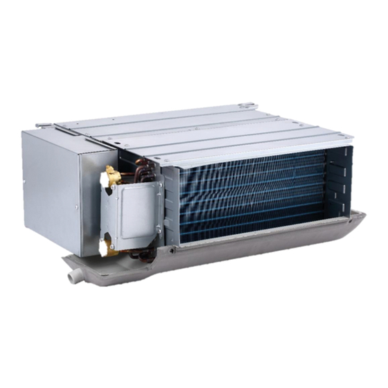
- Page 1 2 PIPES DUCT FAN COIL SERVICE SF2-XXXD3 AIR CONDITIONING...
- Page 2 “Original instructions” IMPORTANT NOTE: Read this manual ca r efully befo r e installing or operating your new air conditioning unit. Make sure to save this manual for future reference.
- Page 3 CONTENTS Part 1 General Information ................3 Part 2 Performance ..................7 Part 3 Accessories ..................67...
-
Page 5: General Information
Part 1 General Information 1 Product lineup ......................4 2 Nomenclature ......................5... -
Page 6: Product Lineup
1 Product lineup Model Power supply Appearance SF2-200D3 220-240V~1N~50Hz SF2-300D3 SF2-400D3 SF2-500D3 220-240V~1N~50Hz SF2-600D3 SF2-700D3 SF2-800D3 220-240V~1N~50Hz SF2-1000D3 SF2-1200D3 220-240V~1N~50Hz SF2-1400D3... - Page 7 2 Nomenclature S F 2 – 200 Nominal Air Volume (200CFM); Type Code 2nd generation Fan Coil Unit Sinclair...
- Page 9 ..................................................................................................................................................
- Page 10 SF2-200D3 SF2-300D3 SF2-400D3 Model name 220-240V/1/50 Power supply V/Ph/Hz 226/251/276/301/ 305/345/383/424/ 446/498/555/602/ 324.5/351/377 463/501.5/542 648/690/735 Air flow 133/148/162/177/ 179/203/225/249/ 262/293/326/354/ 191/206/222 272/295/319 381/406/432 12Pa (default); Standard external static pressure 30/50Pa a can be set through dial switch on the PCB or by wired controller Capacity (H/M/L) Cooling Water flow rate (H/M/L)
- Page 11 SF2-500D3 SF2-600D3 Model name 220-240V/1/50 Power supply V/Ph/Hz 475/536/592/635/ 576/653/733/815/ 687/741/789 888/966/1042 Air flow 279/315/348/374/ 339/384/431/479/ 404/436/464 522/568/613 12Pa (default); Standard external static pressure 30/50Pa a can be set through dial switch on the PCB or by wired controller 4.55/3.92/2.97 5.85/4.88/3.66 Capacity (H/M/L) 23.00/18.96/12.11...
- Page 12 SF2-700D3 SF2-1000D3 SF2-800D3 Model name 220-240V/1/50 Power supply V/Ph/Hz 844/903/968/1031/ 816/901/993/1093/ 740/899/1048/1204/ 1091/1151/1218 1190/1283/1381 1360/1510/1665 Air flow 496/531/569/606/ 480/530/584/643/ 435/529/616/708/ 642/677/716 700/755/812 800/888/979 12Pa (default); Standard external static pressure 30/50Pa a can be set through dial switch on the PCB or by wired controller 6.50/6.04/5.09 8.02/6.65/5.37 9.05/7.10/4.97...
- Page 13 SF2-1400D3 SF2-1200D3 Model name 220-240V/1/50 Power supply V/Ph/Hz 1028/1144/1268/1379/ 1670/1761/1864/1943/ 1490/1604/1720 2058/2137/2202 Air flow 605/673/746/811/ 982/1036/1096/1143 876/944/1012 1211/1257/1295 12Pa (default); Standard external static pressure 30/50Pa a can be set through dial switch on the PCB or by wired controller 10.08/7.25/6.02 11.11/10.58/9.77 Capacity (H/M/L) 27.0/20.7/14.0...
- Page 14 2 Dimensions Model 1200 1400 Size 1025 1215 1505 1745 1183 1473 1713 1182 1472 1712 1155 1445 1685 1003 1178 1368 1658 1898 1063 1253 1543 1783...
-
Page 15: Capacity Tables
3 Capacity Tables Cooling Capacity Table SF2-200D3 Indoor temperature (D.B.) Indoor EWT ΔT temp (W.B.) °C °C °C 2.06 1.54 0.59 31.04 2.05 1.74 0.59 30.70 2.07 1.96 0.59 31.39 2.18 2.17 0.62 34.16 2.38 2.38 0.68 39.94 2.70 1.55 0.78 50.20 2.68 1.76 0.77 49.61 2.66 1.96 0.77 49.04 2.65 2.17 0.76 48.47 2.64 2.37 0.76 48.14 3.36 1.77 0.97 73.53 3.34 1.98 0.96 72.69 3.31 2.18 0.95 70.87 3.29 2.38 0.94 70.09 3.72 1.77 1.07 86.59 3.69 1.98 1.06 85.62 3.67 2.18 1.05 84.68 3.65 2.39 1.05 83.77 1.85 1.44 0.40 15.80 1.88 1.66 0.40 16.12 1.95 1.88 0.42 17.43 2.10 2.10 0.45 19.80 2.31 2.31 0.49 23.01... - Page 16 (Continued) SF2-200D3 Indoor temperature (D.B.) Indoor ΔT temp (W.B.) °C °C °C 1.15 1.10 0.33 11.20 1.33 1.33 0.38 14.27 1.54 1.54 0.44 18.42 1.75 1.75 0.50 22.93 1.96 1.96 0.57 28.17 1.71 1.10 0.49 22.02 1.70 1.31 0.49 21.71 1.72 1.53 0.49 22.14 1.79 1.75...
- Page 17 (Continued) SF2-200D3 Indoor temperature (D.B.) Indoor EWT ΔT temp (W.B.) °C °C °C kW m kW m kW m kW m kW m 0.66 0.66 0.19 3.50 0.89 0.89 0.26 6.99 1.11 1.11 0.32 10.22 1.33 1.33 0.38 13.63 1.54 1.54 0.44 17.81 0.68 0.66 0.20 3.75 0.89 0.89 0.26 7.00...
- Page 18 Heating Capacity Table SF2-200D3 Indoor temperature (W.B.) ΔT °C °C 2.42 0.26 6.28 2.16 0.23 5.19 1.91 0.21 4.18 1.65 0.18 3.27 2.27 0.20 3.89 2.01 0.17 3.15 1.73 0.15 2.42 1.47 0.13 1.62 2.10 0.15 2.45 1.82 0.13 1.76 1.56 0.11 1.15...
- Page 19 Cooling Capacity Table SF2-300D3 Indoor temperature (D.B.) Indoor EWT ΔT temp (W.B.) °C °C °C 2.83 2.13 0.81 32.48 2.82 2.43 0.81 32.15 2.86 2.73 0.82 33.11 3.03 3.03 0.87 36.55 3.32 3.32 0.95 42.72 3.73 2.15 1.07 52.34 3.71 2.44 1.06 51.69 3.68 2.73 1.05 51.04 3.66 3.02 1.05 50.88 3.65 3.31 1.05 50.86 4.67 2.46 1.34 77.73 4.64 2.75 1.34 77.37 4.60 3.04 1.33 76.41 4.57 3.32 1.32 75.50 5.17 2.46 1.50 93.71 5.14 2.76 1.49 92.70 5.10 3.04 1.48 91.59 5.07 3.33 1.47 90.50 2.52 1.99 0.54 16.16 2.57 2.30 0.55 16.84 2.69 2.62 0.58 18.24 2.92 2.92 0.63 21.05 3.21 3.21 0.69 24.49...
- Page 20 (Continued) SF2-300D3 Indoor temperature (D.B.) Indoor ΔT temp (W.B.) °C °C °C 1.57 1.52 0.45 11.60 1.84 1.84 0.53 15.19 2.14 2.14 0.62 19.60 2.44 2.44 0.70 24.48 2.73 2.73 0.79 30.13 2.34 1.52 0.67 22.73 2.32 1.82 0.67 22.40 2.35 2.12 0.68 23.04 2.48 2.44...
- Page 21 (Continued) SF2-300D3 Indoor temperature (D.B.) Indoor ΔT temp (W.B.) °C °C °C m3/h kPa m3/h kPa m3/h kPa m3/h kPa m3/h kPa 0.90 0.90 0.26 3.69 1.22 1.22 0.35 7.31 1.54 1.54 0.44 10.77 1.84 1.84 0.52 14.45 2.14 2.14 0.61 18.95 0.92 0.90...
- Page 22 Heating Capacity Table SF2-300D3 Indoor temperature (W.B.) ΔT °C °C 3.52 0.38 7.22 3.14 0.34 5.95 2.76 0.30 4.79 2.39 0.26 3.74 3.30 0.28 4.46 2.91 0.25 3.60 2.52 0.22 2.81 2.12 0.18 1.96 3.04 0.22 2.86 2.63 0.19 2.13 2.24 0.16 1.40...
- Page 23 Cooling Capacity Table SF2-400D3 Indoor temperature (D.B.) Indoor EWT ΔT temp (W.B.) °C °C °C 3.61 2.74 1.03 30.78 3.60 3.13 1.03 30.55 3.68 3.53 1.05 31.74 3.92 3.92 1.12 35.48 4.30 4.30 1.23 41.85 4.79 2.76 1.38 50.78 4.76 3.15 1.37 50.23 4.73 3.53 1.36 49.69 4.70 3.91 1.36 49.14 4.69 4.29 1.35 49.00 6.01 3.17 1.74 75.39 5.97 3.55 1.72 74.60 5.92 3.92 1.68 71.10 5.90 4.30 1.70 73.03 6.66 3.17 1.93 90.54 6.63 3.56 1.92 89.58 6.58 3.94 1.90 88.51 6.54 4.31 1.88 86.42 3.18 2.54 0.68 15.07 3.25 2.95 0.70 15.66 3.44 3.37 0.74 17.40 3.77 3.77 0.81 20.32 4.14 4.14 0.89 23.72...
- Page 24 (Continued) SF2-400D3 Indoor temperature (D.B.) Indoor EWT ΔT temp (W.B.) °C °C °C 2.00 1.95 0.57 10.94 2.36 2.36 0.68 14.54 2.76 2.76 0.79 18.90 3.15 3.15 0.90 23.69 3.53 3.53 1.02 29.27 2.96 1.94 0.85 21.35 2.94 2.33 0.84 21.08 3.01 2.74 0.86 21.88 3.19 3.15 0.92 24.21 3.54 3.54 1.02 29.36 4.22 2.36 1.21 39.31 4.19 2.75 1.21 38.86 4.17 3.13 1.20 38.41 4.14 3.51 1.19 38.04 4.89 2.37 1.41 51.13 4.86 2.76 1.41 50.94 4.83 3.15 1.40 50.37 4.80 3.52 1.39 49.81 1.77 1.77 0.38...
- Page 25 (Continued) SF2-400D3 Indoor temperature (D.B.) Indoor EWT ΔT temp (W.B.) °C °C °C 1.15 1.15 0.33 3.50 1.56 1.56 0.45 6.95 1.97 1.97 0.57 10.33 2.37 2.37 0.68 13.93 2.76 2.76 0.79 18.36 1.16 1.14 0.33 3.59 1.56 1.56 0.45 6.97 1.97 1.97 0.57 10.36 2.37 2.37 0.68...
- Page 26 Heating Capacity Table SF2-400D3 Indoor temperature (W.B.) ΔT °C °C 4.46 0.48 6.79 3.98 0.43 5.59 3.50 0.38 4.49 3.01 0.32 3.48 4.16 0.36 4.14 3.66 0.32 3.34 3.15 0.27 2.58 2.64 0.23 1.78 3.80 0.27 2.62 3.28 0.24 1.93 2.78 0.20 1.26...
- Page 27 Cooling Capacity Table SF2-500D3 Indoor temperature (D.B.) Indoor EWT ΔT temp (W.B.) °C °C °C kW m kW m kW m kW m kW m 3.86 2.93 1.10 36.91 3.84 3.34 1.10 36.63 3.92 3.77 1.12 38.05 4.19 4.19 1.20 42.66 4.60 4.60 1.33 50.74...
- Page 28 (Continued) SF2-500D3 Indoor temperature (D.B.) Indoor EWT ΔT temp (W.B.) °C °C °C 2.14 2.09 0.61 13.11 2.53 2.53 0.73 17.41 2.95 2.95 0.85 22.70 3.37 3.37 0.97 28.88 3.77 3.77 1.08 34.73 3.17 2.07 0.91 25.60 3.14 2.49 0.90 25.25 3.22 2.93 0.93 26.64 3.41 3.37 0.99 29.49 3.78 3.78 1.09 34.82 4.52 2.52 1.31 47.95 4.49 2.94 1.30 47.41 4.46 3.35 1.29 46.86 4.43 3.76 1.28 46.41 5.23 2.54 1.52 61.96 5.20 2.95 1.51 61.27 5.15 3.36 1.48 59.65 5.12 3.76 1.47 58.97 1.89 1.89 0.41...
- Page 29 (Continued) SF2-500D3 Indoor temperature (D.B.) Indoor EWT ΔT temp (W.B.) °C °C °C 1.22 1.22 0.35 4.42 1.67 1.67 0.48 8.34 2.11 2.11 0.61 12.39 2.53 2.53 0.73 16.97 2.95 2.95 0.85 22.05 1.23 1.22 0.35 4.51 1.67 1.67 0.48 8.36 2.11 2.11 0.61 12.42 2.54 2.54 0.73...
- Page 30 Heating Capacity Table SF2-500D3 Indoor temperature (W.B.) ΔT °C °C 4.92 0.53 8.64 4.39 0.47 7.08 3.86 0.42 5.70 3.32 0.36 4.43 4.60 0.40 5.27 4.06 0.35 4.25 3.50 0.30 3.32 2.94 0.25 2.42 4.23 0.30 3.38 3.65 0.26 2.60 3.08 0.22 1.77...
- Page 31 Cooling Capacity Table SF2-600D3 Indoor temperature (D.B.) Indoor EWT ΔT temp (W.B.) °C °C °C kW m kW m kW m kW m kW m 4.88 3.69 1.40 58.63 4.86 4.20 1.39 58.05 4.94 4.73 1.42 59.94 5.27 5.26 1.52 67.74 5.77 5.77 1.65 78.48...
- Page 32 (Continued) SF2-600D3 Indoor temperature (D.B.) Indoor ΔT temp (W.B.) °C °C °C 2.72 2.63 0.78 20.83 3.19 3.19 0.92 27.71 3.71 3.71 1.07 35.56 4.23 4.23 1.23 45.23 4.74 4.74 1.36 54.39 4.03 2.62 1.16 40.97 4.00 3.14 1.15 40.42 4.07 3.68 1.18 42.21 4.29 4.23 1.24 46.36 4.75 4.75 1.37 54.55...
- Page 33 (Continued) SF2-600D3 Indoor temperature (D.B.) Indoor EWT ΔT temp (W.B.) °C °C °C kW m kW m kW m kW m kW m 1.56 1.56 0.45 7.83 2.11 2.11 0.60 12.98 2.66 2.66 0.76 19.47 3.19 3.19 0.91 26.48 3.70 3.70 1.06 34.08 1.58 1.55 0.45 8.03 2.12 2.12 0.60 13.01 2.66 2.66 0.77 19.52 3.19 3.19 0.92 26.53 3.71 3.71 1.06 34.17 2.87 2.07 0.83 22.20 2.99 2.62 0.86 23.85 3.26 3.18 0.93 27.32 3.71 3.71 1.06 34.24...
- Page 34 Heating Capacity Table SF2-600D3 Indoor temperature (W.B.) ΔT °C °C 6.20 0.67 13.55 5.54 0.60 11.18 4.88 0.53 9.00 4.22 0.46 6.98 5.81 0.50 8.29 5.14 0.44 6.71 4.46 0.38 5.27 3.76 0.32 3.95 5.37 0.39 5.36 4.67 0.34 4.22 3.94 0.28 3.16...
- Page 35 Cooling Capacity Table SF2-700D3 Indoor temperature (D.B.) Indoor EWT ΔT temp (W.B.) °C °C °C kW m kW m kW m kW m kW m 5.57 4.24 1.59 38.07 5.54 4.85 1.59 37.81 5.68 5.47 1.63 39.49 6.09 6.08 1.74 44.47 6.68 6.68 1.91 52.24...
- Page 36 (Continued) SF2-700D3 Indoor temperature (D.B.) Indoor EWT ΔT temp (W.B.) °C °C °C kW m kW m kW m kW m kW m 3.09 3.02 0.89 13.49 3.66 3.66 1.05 18.06 4.28 4.28 1.23 23.59 4.89 4.89 1.41 30.07 5.48 5.48 1.58 36.20 4.56 3.00 1.32 26.52 4.52 3.61 1.30 25.95 4.64 4.25 1.34 27.48 4.94 4.89 1.43 30.61 5.49 5.49 1.58 36.30 6.52 3.66 1.89 49.54 6.48 4.26 1.88 48.99 6.44 4.86 1.87 48.44 6.41 5.46 1.86 48.01 7.55 3.66 2.17 63.15 7.51 4.27 2.17 62.79 7.47 4.88 2.17 62.72 7.42 5.47 2.15 62.10...
- Page 37 (Continued) SF2-700D3 Indoor temperature (D.B.) Indoor EWT ΔT temp (W.B.) °C °C °C kW m kW m kW m kW m kW m 1.75 1.75 0.50 4.63 2.41 2.41 0.69 8.61 3.04 3.04 0.87 12.64 3.67 3.67 1.05 17.63 4.28 4.28 1.23 22.94 1.76 1.75 0.51 4.70 2.42 2.42 0.69 8.63...
- Page 38 Heating Capacity Table SF2-700D3 Indoor temperature (W.B.) ΔT °C °C 6.59 0.71 7.80 5.86 0.63 6.38 5.13 0.55 5.08 4.39 0.47 3.90 6.06 0.52 4.67 5.32 0.46 3.73 4.55 0.39 2.86 3.76 0.32 1.96 5.47 0.39 2.90 4.68 0.34 2.12 3.94 0.28 1.36...
- Page 39 Cooling Capacity Table SF2-800D3 Indoor temperature (D.B.) Indoor EWT ΔT temp (W.B.) °C °C °C kW m kW m kW m kW m kW m 6.69 5.05 1.92 58.16 6.65 5.76 1.90 57.59 6.77 6.48 1.94 59.45 7.21 7.21 2.08 67.21 7.90 7.90 2.27 77.82...
- Page 40 (Continued) SF2-800D3 Indoor temperature (D.B.) Indoor EWT ΔT temp (W.B.) °C °C °C kW m kW m kW m kW m kW m 3.72 3.61 1.07 20.66 4.37 4.37 1.26 27.49 5.08 5.08 1.46 35.27 5.79 5.79 1.68 44.85 6.49 6.49 1.87 53.93 5.52 3.59 1.59 40.64 5.47 4.31 1.57 40.10 5.56 5.04 1.60 41.21 5.88 5.79 1.70 45.97 6.50 6.50 1.87 54.08 7.81 4.35 2.27 75.45 7.76 5.06 2.25 74.61 7.71 5.77 2.24 73.80 7.66 6.46 2.22 72.98 9.01 4.36 2.60 95.90 8.95 5.08 2.59 94.84 8.90 5.78 2.58 94.28 8.86 6.48 2.58 94.26...
- Page 41 (Continued) SF2-800D3 Indoor temperature (D.B.) Indoor EWT ΔT temp (W.B.) °C °C °C kW m kW m kW m kW m kW m 2.13 2.13 0.61 7.76 2.89 2.89 0.83 12.88 3.64 3.64 1.05 19.31 4.36 4.36 1.25 26.33 5.07 5.07 1.45 33.80 2.16 2.13 0.62 7.96 2.90 2.90 0.83 12.90 3.65 3.65 1.05 19.36 4.37 4.37 1.26 26.38 5.08 5.08 1.45 33.89 3.93 2.83 1.13 22.02 4.10 3.59 1.18 23.65 4.47 4.36 1.28 27.11 5.09 5.08 1.45 33.96...
- Page 42 Heating Capacity Table SF2-800D3 Indoor temperature (W.B.) ΔT °C °C 8.33 0.90 13.03 7.45 0.81 10.74 6.56 0.71 8.64 5.66 0.61 6.68 7.80 0.67 7.94 6.88 0.59 6.42 5.96 0.51 5.03 5.01 0.43 3.75 7.19 0.52 5.11 6.23 0.45 4.02 5.24 0.38 2.97...
- Page 43 Cooling Capacity Table SF2-1000D3 Indoor temperature (D.B.) Indoor EWT ΔT temp (W.B.) °C °C °C kW m kW m kW m kW m kW m 7.61 5.78 2.18 54.14 7.58 6.61 2.17 53.68 7.75 7.45 2.22 55.79 8.29 8.29 2.39 63.67 9.10 9.10 2.63 74.83...
- Page 44 (Continued) SF2-1000D3 Indoor temperature (D.B.) Indoor EWT ΔT temp (W.B.) °C °C °C kW m kW m kW m kW m kW m 4.23 4.12 1.21 19.17 4.99 4.99 1.43 25.49 5.83 5.83 1.67 33.27 6.66 6.66 1.93 42.42 7.46 7.46 2.15 51.11 6.25 4.10 1.80 37.52 6.20 4.93 1.78 37.04...
- Page 45 (Continued) SF2-1000D3 Indoor temperature (D.B.) Indoor EWT ΔT temp (W.B.) °C °C °C 2.41 2.41 0.69 7.16 3.31 3.31 0.95 12.21 4.17 4.17 1.20 18.13 5.00 5.00 1.44 24.85 5.82 5.82 1.66 31.93 2.44 2.41 0.70 7.27 3.31 3.31 0.95 12.24 4.17 4.17 1.20 18.18 5.01 5.01 1.44 24.92 5.83 5.83 1.67 32.01...
- Page 46 Heating Capacity Table SF2-1000D3 Indoor temperature (W.B.) ΔT °C °C 9.64 1.04 12.48 8.61 0.93 10.26 7.56 0.82 8.24 6.52 0.70 6.36 8.99 0.78 7.56 7.93 0.68 6.10 6.85 0.59 4.76 5.74 0.50 3.53 8.26 0.59 4.84 7.14 0.51 3.78 5.98 0.43 2.78...
- Page 47 Cooling Capacity Table SF2-1200D3 Indoor temperature (D.B.) Indoor EWT ΔT temp (W.B.) °C °C °C kW m kW m kW m kW m 8.49 6.42 2.43 44.14 8.44 7.33 2.42 43.75 8.62 8.26 2.48 45.67 9.19 9.18 2.63 50.86 10.07 10.07 2.88 59.47 11.24 6.47 3.25 72.88 11.17 7.38 3.23 72.10 11.08 8.26 3.18...
- Page 48 (Continued) SF2-1200D3 Indoor temperature (D.B.) Indoor EWT ΔT temp (W.B.) °C °C °C kW m kW m kW m kW m kW m 4.72 4.59 1.36 15.82 5.55 5.55 1.59 20.71 6.48 6.48 1.87 27.37 7.38 7.38 2.12 33.84 8.28 8.28 2.40 41.83 7.00 4.57 2.03 31.28 6.95 5.48 2.01 30.87...
- Page 49 (Continued) SF2-1200D3 Indoor temperature (D.B.) Indoor EWT ΔT temp (W.B.) °C °C °C 2.69 2.69 0.77 5.68 3.68 3.68 1.06 9.97 4.62 4.62 1.32 14.53 5.56 5.56 1.60 20.18 6.47 6.47 1.86 26.20 2.72 2.68 0.78 5.82 3.68 3.68 1.06 9.99 4.63 4.63 1.32 14.57 5.57 5.57 1.60...
- Page 50 Heating Capacity Table SF2-1200D3 Indoor temperature (W.B.) ΔT °C °C 10.59 1.15 9.94 9.45 1.02 8.14 8.31 0.90 6.54 7.17 0.77 5.08 9.90 0.85 6.05 8.73 0.75 4.88 7.54 0.65 3.81 6.32 0.55 2.82 9.09 0.65 3.88 7.85 0.57 3.02 6.60 0.48 2.12...
- Page 51 Cooling Capacity Table SF2-1400D3 Indoor temperature (D.B.) Indoor EWT ΔT temp (W.B.) °C °C °C kW m /h kPa kW m kW m 9.44 7.22 2.70 57.57 9.39 8.27 2.69 57.13 9.65 9.34 2.76 59.85 10.40 10.40 2.98 68.30 11.42 11.42 3.28 80.47 12.55 7.26 3.61 94.90 12.48 8.30 3.59 93.97 12.42 9.34 3.58 93.73 12.37 10.38 3.58 93.61 12.35 11.40 3.57 93.41 15.84 8.35 4.59 144.65 15.76 9.39 4.58 143.92 15.65 10.40 4.53 141.23 15.57 11.43 4.50 139.39...
- Page 52 (Continued) SF2-1400D3 Indoor temperature (D.B.) Indoor EWT ΔT temp (W.B.) °C °C °C kW m kW m kW m kW m kW m 5.22 5.14 1.50 20.26 6.24 6.24 1.80 27.82 7.29 7.29 2.09 35.93 8.34 8.34 2.42 45.98 9.36 9.36 2.70 55.55 7.70 5.10 2.21 39.47 7.64 6.15 2.20 38.95...
- Page 53 (Continued) SF2-1400D3 Indoor temperature (D.B.) Indoor EWT ΔT temp (W.B.) °C °C °C kW m kW m kW m kW m kW m 2.97 2.97 0.85 7.49 4.09 4.09 1.17 12.77 5.19 5.19 1.49 19.43 6.25 6.25 1.79 26.61 7.29 7.29 2.08 34.57 2.98 2.97 0.86 7.55 4.09 4.09 1.17 12.80 5.19 5.19 1.49 19.48 6.25 6.25 1.79 26.66 7.30 7.30 2.09 34.65 5.36 4.01 1.54 20.57 5.69 5.13 1.64 22.78 6.33 6.25 1.81 27.09 7.31 7.31 2.09 34.74...
- Page 54 Heating Capacity Table SF2-1400D3 Indoor temperature (W.B.) ΔT °C °C 10.82 1.17 11.20 9.61 1.04 9.13 8.38 0.90 7.19 7.15 0.77 5.49 9.90 0.85 6.57 8.64 0.75 5.22 7.37 0.64 3.98 6.05 0.52 2.83 8.86 0.64 4.03 7.52 0.54 3.04 6.22 0.45 1.99...
- Page 55 4 Octave Band Levels Test condition 1000mm 1000mm 1-Damping net 2-Duct 3-Static pressure loop 4-Test unit -Equivalent diameter of air return of the unit SF2-200D3 Fan speed 7(H) Fan speed 6 Fan speed 5 Fan speed 4(M) Fan speed 3 Fan speed 2 Fan speed 1(L) NC-70...
- Page 56 SF2-300D3 Fan speed 7(H) Fan speed 6 Fan speed 5 Fan speed 4(M) Fan speed 3 Fan speed 2 Fan speed 1(L) NC-70 NC-60 NC-50 NC-40 NC-30 NC-20 1000 2000 4000 8000 Octave band central frequency (Hz) SF2-400D3 Fan speed 7(H) Fan speed 6 Fan speed 5 Fan speed 4(M)
- Page 57 SF2-500D3 Fan speed 7(H) Fan speed 6 Fan speed 5 Fan speed 4(M) Fan speed 3 Fan speed 2 Fan speed 1(L) NC-70 NC-60 NC-50 NC-40 NC-30 NC-20 1000 2000 4000 8000 Octave band central frequency (Hz) SF2-600D3 Fan speed 7(H) Fan speed 6 Fan speed 5 Fan speed 4(M)
- Page 58 SF2-700D3 Fan speed 7(H) Fan speed 6 Fan speed 5 Fan speed 4(M) Fan speed 3 Fan speed 2 Fan speed 1(L) NC-70 NC-60 NC-50 NC-40 NC-30 NC-20 1000 2000 4000 8000 Octave band central frequency (Hz) SF2-800D3 Fan speed 7(H) Fan speed 6 Fan speed 5 Fan speed 4(M)
- Page 59 SF2-1000D3 Fan speed 7(H) Fan speed 6 Fan speed 5 Fan speed 4(M) Fan speed 3 Fan speed 2 Fan speed 1(L) NC-70 NC-60 NC-50 NC-40 NC-30 NC-20 1000 2000 4000 8000 Octave band central frequency (Hz) SF2-1200D3 Fan speed 7(H) Fan speed 6 Fan speed 5 Fan speed 4(M)
- Page 60 SF2-1400D3 Fan speed 7(H) Fan speed 6 Fan speed 5 Fan speed 4(M) Fan speed 3 Fan speed 2 Fan speed 1(L) NC-70 NC-60 NC-50 NC-40 NC-30 NC-20 1000 2000 4000 8000 Octave band central frequency (Hz)
- Page 61 5 Static Pressure Graphs Models of 12Pa standard external static pressure SF2-200D3 SF2-300D3...
- Page 62 SF2-400D3 SF2-500D3...
- Page 63 SF2-600D3 SF2-700D3...
- Page 64 SF2-800D3 SF2-1000D3...
- Page 65 SF2-1200D3 SF2-1400D3...
-
Page 66: Wiring Diagrams
6 Wiring Diagrams SF2-400-1400D3... -
Page 67: Electrical Characteristic
7 Electrical Characteristic Units Power Supply Model name (Indoor Fan Motor) Volts (V) Min. (V) Max. (V) MCA (A) MFA (A) KW (W) FLA (A) 220-240 0.23 0.18 SF2-200D3 220-240 0.29 0.23 SF2-300D3 220-240 0.39 0.31 SF2-400D3 SF2-500D3 220-240 0.44 0.35 SF2-600D3 220-240... - Page 69 Part 3 Accessories 1 Standard Accessories ....................68 2 Optional Accessories ....................68...
-
Page 70: Standard Accessories
1 Standard Accessories Accessory name Qty. Shape Usage Owner’s & installation manual Installation guide 2 Optional Accessories Accessory name Qty. Shape Usage Remote controller Remote control RM05 Remote controller Remote control R51/E Wired controller Wired control SWC-61 Centralized controller Centralized control CCM30/SCM-30 1.1 Optional remote controller: RM05 1.1.1 Operation section... - Page 71 1.1.2 Display section 1.1.2.1 How to operate • MODE: Once pressing, running mode will be selected in the following sequence: AUTO COOL HEAT NOTE: No heating mode for cool only type unit. • FAN SPEED: Fan speed will be selected in following sequence once pressing this button: AUTO HIGH •...
- Page 72 • COOL/HEAT (inner located): Press this button with a needle of 1 mm to shift mode between COOL only and COOL&HEAT. During setting, back light will be lightened. Factory default mode is COOL &HEAT. • ECO: Activate or turn off economic operation mode. It is suggested to turn on this function when sleeping. (Only available when remote controller is used with corresponding unit.) 1.1.2.2 Specifications Model...
- Page 73 • FAN SPEED Button: This button is used for setting fan speed in the sequence that goes from AUTO, LOW, MED to HIGH, and then back to Auto. • TEMP UP Button: Push this button to increase the indoor temperature setting or to adjust the timer in a counter-clockwise direction.
- Page 74 CCM30/SCM-30 is new designed and is a touch key centralized controller. It can be connected up to 64 indoor units, and the connection length can be up to 1200m. The CCM30 centralized controller has the air filter cleaning reminding function and it is convenient to remind users to clean the air filter.
- Page 75 (4) Mode key Under the setting operation mode, press this key to set the operation. (5) Fan key Under the setting operation mode, press this key to set the fan of the indoor unit to run in the automatic, high, medium or low level of air.
- Page 76 (13) Add key 1) Query mode: Press this key, display the data of the last page. If it is now in the last page, press this key again and the first page will be displayed. 2) Setting operation mode ①Temperature adjusting method ℃...
- Page 77 2.4.2 LCD display 2.4.3 Liquid crystal matrix display description The liquid crystal matrix is composed of 4×16 grids, and each grid is composed of two blocks of different sizes. The matrix includes horizontal coordinates 00~15 on the upper side and vertical coordinates 00+, 16+, 32+ and 48+ on the left side, which indicate the address of the indoor unit.
- Page 78 the address of the grid. Each grid corresponds to an indoor unit of this address. One grid is composed of two blocks of different sizes. The state indication table is as follows; Status Constantly on Slow blink Fast blink Object Big black block In-service Selected...
- Page 79 Description of the setting page The LCD display displays the setting page, and queries the air conditioner with the address of 01. The mode of the air conditioner with the address 01 is: Cooling, high fan speed, swing on, setting temperature 22°C and cooling. In the matrix, only the big black dots at (00+, 01) to (00+, 15) are luminous.
- Page 80 United Kingdom www.sinclair-world.com This product was manufactured in China (Made in China). R E P R E S E N T A T I V E SINCLAIR Global Group s.r.o. Purkynova 45 612 00 Brno Czech Republic T E C H N I C A L S U P P O R T SINCLAIR Global Group s.r.o.
Need help?
Do you have a question about the SF2 D3 Series and is the answer not in the manual?
Questions and answers