Table of Contents
Advertisement
Quick Links
Advertisement
Table of Contents

Related Manuals for Sinclair SF D4 Series


Summary of Contents for Sinclair SF D4 Series
- Page 1 4 PIPES DUCT FAN COIL SERVICE MANUAL SF-XXXD4 AIR CONDITIONING...
- Page 2 “Original instructions” IMPORTANT NOTE: Read this manual ca r efully befo r e installing or operating your new air conditioning unit. Make sure to save this manual for future reference.
-
Page 3: Table Of Contents
Content 1. External Appearance ............... 2 2. Feature ..................2 3. Product Lineup ................ 4 4. Accessories ................4 5. Specifications ................5 6. Capacity Table ................. 8 7. Dimensions ................32 8. Sound Levels ................. 33 9. Space Requirement ............... 38 10. -
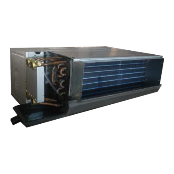
Page 4: External Appearance
1. External Appearance 2. Feature Wider external static pressure supplying. The factory default 12Pa, 30/50Pa can adjust in the field. Left or right hand piping connections, field convertible. Quiet operation A patent design is able to prevent abnormal noise caused by blowing fins. ... - Page 5 220-240V/1Ph/50Hz power supply is standard and 208-230V/1Ph/60Hz can be customized. Excellent efficiency Sinclair DC FCUs use the brushless DC motor, the DC motor efficiency up to 90%. Contrast with the original FCU. DC FCU power consumption can be reduced by about 30%. ...
-
Page 6: Product Lineup
3. Product Lineup Air volume External static pressure Electric Series Model Power supply (CFM) (Pa) heater SF-200D4 SF-300D4 SF-400D4 SF-500D4 220~240V-1Ph- 3-row Duct Without 50Hz SF-600D4 SF-800D4 SF-1000D4 1000 SF-1200D4 1200 Note: The units with electric heater can be customized. 4. -
Page 7: Specifications
5. Specifications Model SF-200D4 SF-300D4 SF-400D4 H/M/L 320/210/140 450/340/280 530/390/260 Air flow (12,30,50Pa) H/M/L 190/120/85 270/200/170 320/230/160 External Static pressure The factory default 12Pa,30/50Pa can adjust in the field Capacity(12,30,50Pa) H/M/L 1.4/1.1/0.8 2.2/1.7/1.5 2.5/2.0/1.5 Cooling Water flow rate Water pressure drop 10.2 10.5 11.3... - Page 8 Specification Model SF-500D4 SF-600D4 SF-800D4 H/M/L 690/470/370 900/670/440 1240/840/670 Air flow (12,30,50Pa) H/M/L 410/280/220 530/400/260 730/500/400 External Static pressure The factory default 12Pa,30/50Pa can adjust in the field Capacity(12,30,50Pa) H/M/L 3.0/2.4/1.9 4.2/3.5/2.5 5.3/4.1/3.1 Cooling Water flow rate Water pressure drop 13.6 15.3 12.8...
- Page 9 Specification Model SF-1000D4 SF-1200D4 H/M/L 1610/1160/790 1850/1400/970 Air flow (12,30,50Pa) H/M/L 950/690/470 1090/830/570 External Static pressure The factory default 12Pa, 30/50Pa can adjust in the field Capacity(12,30,50Pa) H/M/L 6.7/5.4/3.9 8.2/6.5/4.6 Cooling Water flow rate 1180 1400 Water pressure drop 21.6 34.9 Capacity(12,30,50Pa) H/M/L...
-
Page 10: Capacity Table
6. Capacity Table Cooling Capacity Table SF-200D4 Indoor Indoor temperature (D.B.) EWT ΔT temp (W.B.) SC WF WPD TC SC WF WPD TC SC WF WPD TC SC WF WPD TC SC WF WPD ° C ° C ° C kW kW m /h kPa kW kW m... - Page 11 (Continued) SF-200D4 Indoor Indoor temperature (D.B.) EWT ΔT temp (W.B.) WF WPD TC WF WPD TC WF WPD TC WF WPD TC WF WPD ° C ° C ° C kW m /h kPa kW m /h kPa kW m /h kPa kW m /h kPa...
- Page 12 SF-300D4 Indoor Indoor temperature (D.B.) EWT ΔT temp (W.B.) SC WF WPD TC SC WF WPD TC SC WF WPD TC SC WF WPD TC SC WF WPD ° C ° C ° C kW kW m /h kPa kW kW m /h kPa kW kW m /h kPa...
- Page 13 (Continued) SF-300D4 Indoor Indoor temperature (D.B.) EWT ΔT temp (W.B.) SC WF WPD TC SC WF WPD TC SC WF WPD TC SC WF WPD TC SC WF WPD ° C ° C ° C kW kW m /h kPa kW kW m /h kPa kW kW m...
- Page 14 SF-400D4 Indoor Indoor temperature (D.B.) EWT ΔT temp (W.B.) SC WF WPD TC SC WF WPD TC SC WF WPD TC SC WF WPD TC SC WF WPD ° C ° C ° C kW kW m /h kPa kW kW m /h kPa kW kW m /h kPa...
- Page 15 (Continued) SF-400D4 Indoor Indoor temperature (D.B.) EWT ΔT temp (W.B.) WF WPD TC WF WPD TC WF WPD TC WF WPD TC WF WPD ° C ° C ° C kW m /h kPa kW m /h kPa kW m /h kPa kW m /h kPa...
- Page 16 SF-500D4 Indoor Indoor temperature (D.B.) EWT ΔT temp (W.B.) SC WF WPD TC SC WF WPD TC SC WF WPD TC SC WF WPD TC SC WF WPD ° C ° C ° C kW kW m /h kPa kW kW m /h kPa kW kW m /h kPa...
- Page 17 (Continued) SF-500D4 Indoor Indoor temperature (D.B.) EWT ΔT temp (W.B.) SC WF WPD TC SC WF WPD TC SC WF WPD TC SC WF WPD TC SC WF WPD ° C ° C ° C kW kW m /h kPa kW kW m /h kPa kW kW m...
- Page 18 SF-600D4 Indoor Indoor temperature (D.B.) EWT ΔT temp (W.B.) SC WF WPD TC SC WF WPD TC SC WF WPD TC SC WF WPD TC SC WF WPD ° C ° C ° C kW kW m /h kPa kW kW m /h kPa kW kW m /h kPa...
- Page 19 (Continued) SF-600D4 Indoor Indoor temperature (D.B.) EWT ΔT temp (W.B.) SC WF WPD TC SC WF WPD TC SC WF WPD TC SC WF WPD TC SC WF WPD ° C ° C ° C kW kW m /h kPa kW kW m /h kPa kW kW m...
- Page 20 SF-800D4 Indoor Indoor temperature (D.B.) EWT ΔT temp (W.B.) SC WF WPD TC SC WF WPD TC SC WF WPD TC SC WF WPD TC SC WF WPD ° C ° C ° C kW kW m /h kPa kW kW m /h kPa kW kW m /h kPa...
- Page 21 (Continued) SF-800D4 Indoor Indoor temperature (D.B.) EWT ΔT temp (W.B.) SC WF WPD TC SC WF WPD TC SC WF WPD TC SC WF WPD TC SC WF WPD ° C ° C ° C kW kW m /h kPa kW kW m /h kPa kW kW m...
- Page 22 SF-1000D4 Indoor Indoor temperature (D.B.) EWT ΔT temp (W.B.) TC SC WF WPD TC SC WF WPD SC WF WPD SC WF WPD SC WF WPD ° C ° C ° C kW kW m /h kPa kW m /h kPa kW m /h kPa kW m...
- Page 23 (Continued) SF-1000D4 Indoor Indoor temperature (D.B.) EWT ΔT temp (W.B.) SC WF WPD TC SC WF WPD TC SC WF WPD TC SC WF WPD TC SC WF WPD ° C ° C ° C kW kW m /h kPa kW kW m /h kPa kW kW m...
- Page 24 SF-1200D4 Indoor Indoor temperature (D.B.) EWT ΔT temp (W.B.) TC SC WF WPD TC SC WF WPD SC WF WPD SC WF WPD SC WF WPD ° C ° C ° C kW kW m /h kPa kW m /h kPa kW m /h kPa kW m...
- Page 25 (Continued) SF-1200D4 Indoor Indoor temperature (D.B.) EWT ΔT temp (W.B.) SC WF WPD TC SC WF WPD TC SC WF WPD TC SC WF WPD TC SC WF WPD ° C ° C ° C kW kW m /h kPa kW kW m /h kPa kW kW m...
- Page 26 Heating Capacity Table SF-200D4 Indoor temperature (W.B.) ΔT ° C ° C 0.92 0.10 1.72 0.80 0.09 1.35 0.68 0.07 1.01 0.55 0.06 0.65 0.78 0.07 0.86 0.66 0.06 0.57 0.55 0.05 0.35 0.45 0.04 0.22 0.66 0.05 0.35 0.56 0.04 0.24 0.44...
- Page 27 SF-300D4 Indoor temperature (W.B.) ΔT ° C ° C 1.36 0.15 3.96 1.19 0.13 3.14 1.02 0.11 2.41 0.84 0.09 1.75 1.19 0.10 2.16 1.01 0.09 1.64 0.83 0.07 1.17 0.66 0.06 0.68 1.00 0.07 1.16 0.83 0.06 0.74 0.67 0.05 0.42 0.51...
- Page 28 SF-400D4 Indoor temperature (W.B.) ΔT ° C ° C 1.67 0.18 6.53 1.46 0.16 5.20 1.26 0.14 4.01 1.05 0.11 2.94 1.47 0.13 3.60 1.26 0.11 2.77 1.05 0.09 2.03 0.83 0.07 1.36 1.26 0.09 2.06 1.04 0.08 1.48 0.84 0.06 0.88 0.65...
- Page 29 SF-500D4 Indoor temperature (W.B.) ΔT ° C ° C 2.03 0.22 9.17 1.78 0.19 7.28 1.53 0.17 5.62 1.28 0.14 4.16 1.80 0.15 5.06 1.54 0.13 3.92 1.29 0.11 2.89 1.04 0.09 1.99 1.55 0.11 2.92 1.29 0.09 2.15 1.03 0.07 1.45 0.78...
- Page 30 SF-600D4 Indoor temperature (W.B.) ΔT ° C ° C 2.61 0.28 18.49 2.30 0.25 14.82 1.99 0.22 11.51 1.68 0.18 8.57 2.33 0.20 10.33 2.02 0.17 8.04 1.70 0.15 6.00 1.38 0.12 4.20 2.04 0.15 6.07 1.72 0.12 4.53 1.39 0.10 3.17 1.06...
- Page 31 SF-800D4 Indoor temperature (W.B.) ΔT ° C ° C 3.01 0.33 4.68 2.63 0.28 3.71 2.26 0.24 2.84 1.87 0.20 2.07 2.62 0.23 2.53 2.23 0.19 1.93 1.84 0.16 1.39 1.45 0.13 0.86 2.20 0.16 1.39 1.80 0.13 0.92 1.46 0.11 0.53 1.13...
- Page 32 SF-1000D4 Indoor temperature (W.B.) ΔT ° C ° C 3.68 0.40 7.19 3.23 0.35 5.73 2.77 0.30 4.41 2.32 0.25 3.24 3.24 0.28 3.95 2.77 0.24 3.03 2.31 0.20 2.21 1.83 0.16 1.49 2.76 0.20 2.23 2.28 0.16 1.61 1.80 0.13 0.99 1.39...
- Page 33 SF-1200D4 Indoor temperature (W.B.) ΔT ° C ° C 4.62 0.50 13.02 4.07 0.44 10.42 3.51 0.38 8.02 2.95 0.32 5.94 4.11 0.35 7.22 3.54 0.31 5.60 2.98 0.26 4.15 2.40 0.21 2.88 3.57 0.26 4.19 2.99 0.22 3.10 2.40 0.17 2.14 1.80...
-
Page 34: Dimensions
7. Dimensions Unit: mm Model 400-Model 1000- 1200- 200-Model 300-Model 600-Model 800-Model 500-Model Model Model Size 1265 1370 1660 1205 1310 1600 1233 1338 1628 1205 1310 1600 1161 1461 1566 1856 1003 1303 1408 1698 Notes: The above figure is only an instance model, which would be different from the one that you purchase. ... -
Page 35: Sound Levels
8. Sound Levels 200D3 300D3 400D3 500D3 12Pa (H/M/L) 36/32/26 37/33/26 37/34/27 38/35/28 30Pa (H/M/L) 40/36/29 41/38/30 42/38/31 43/38/32 50Pa (H/M/L) 42/39/31 43/40/32 45/41/33 45/42/34 600D3 800D3 1000D3 1200D3 12Pa (H/M/L) 39/36/29 41/37/30 42/39/32 44/40/33 30Pa (H/M/L) 44/40/33 45/40/34 46/42/34 47/42/34 50Pa (H/M/L) 47/43/35... - Page 36 SF-200D4 SF-300D4...
- Page 37 SF-400D4 SF-500D4...
- Page 38 SF-600D4 SF-800D4...
- Page 39 SF-1000D4 SF-1200D4...
-
Page 40: Space Requirement
9. Space Requirement 10. Main PCB ports Main PCB port description: Bit No. Description Remarks POWER: Mains input Standard HI: Mechanical three-gear wire controller with high speed Standard MED: Mechanical three-speed wire controller with medium speed LOW: Mechanical three-speed wire controller with low speed N: Mechanical three-speed wire controller with null line ALARM: Fault alarm output Customized... -
Page 41: Wiring Diagram
DC_FAN2: DC Fan 2 Standard DC_FAN1: DC Fan 1 Standard EARTH EARTH: Grounding screw position Standard 11. Wiring Diagram... - Page 42 Static pressure 12Pa 30Pa 50Pa Notes: MODE 1. Connection of motor and main 200CFM (34W) control panel: single-motor model single-motor should connect CN5, for double- O F F O F F O F F O F F motor model, positions of CN5 300CFM (51W) and CN8 can be changed.
-
Page 43: Installation
12. Installation 12.1 Installing site Install the unit where installation and maintenance space is enough. Install the unit where the ceiling is horizontal and enough to bear the weight of the indoor unit. Install the unit where the air inlet and outlet are not baffled and are the least affected by external air. ... - Page 44 Old concrete roughcast: Use embedded bolts and embedded pulling plugs. Steel beam and girder structure: Set and use supportive angle steel. New concrete roughcast: Set it with embedded bushes or embedded bolts. Suspending the indoor unit ...
- Page 45 Please hang up the extended drain pan to the pipes or ceiling by a rope. 12.4 Installing water pipe With air release valve, the other side is water inlet pipe. When connect water collector, set the tightening torque to 6180~7540N.cm (630~770kgf.cm), and use a spanner to tighten it as shown in Figure.
-
Page 46: Optional Wired Controller
Drain test Before the test, ensure that the drain pipes are smooth and the adapters are sealed. Newly built rooms should undergo the drain test before the ceiling is laid. 12.6 Wiring installation CAUTIONS: The air conditioner should use separate power supply with rated voltage. ... - Page 47 PART NUMBER: KJR-18B 2-pipe KJR-18B 4-pipe KJR-18B 2-pipe MODEL NO (with constant fun) (with constant fun) ( with fun stop) 2PIPE √ √ (No Valve) 2PIPE √ √ (1 Valve) 4PIPE √ (2 Valves) When When the temperature When the temperature the temperature CONTROL reaches...
-
Page 48: Pcb Control Kit For Fcu
13.4 Wiring diagrams KJR-18B KJR-18B N (220VAC) N (220VAC) L (220VAC) L (220VAC) Valve Val 2 Val 1 Val2 Val1 Med Low 2-wireNCvalve system Val1: For heating Val2: For cooling (KJR-18B without Motorized Valve) 2-wire NC valve system Note: Please confirm the model and use corresponding wiring diagram above when you wire. 14. - Page 49 14.2 Introduction FCUKZ is an independent control box that can connect a FCU to realize centralized control. Control box wiring is as follows: 14.3. Internal View Note: FCUKZ-03 adopts one valve switch, FCUKZ-04 adopts two valve switches. When installing FCUKZ-04 should connect the valve switch (CN12:PIPE-COOL and CN11 :...
- Page 50 ENC1 code 00~15 16~31 32~47 48~63 CN9: Connect to wire controller. CN5: T1, room temperature sensor (if fault, the wire controller light will flashes two times at 2Hz, stop 2s); CN5: T2-COOL, pipe temperature sensor of condenser (if fault, the wire controller light will flashes three times at 2Hz, stop 2s);...
- Page 51 Attention: the control port value of the CN20(HEAT) is STRONG AC signal output but can not drive electric heating directly. So special attention should be paid when installing this heat. Electric heating needs to be connected with 220V-240V~ power supply externally. CN4: HEAT (DC +12V output).
- Page 52 • When dry operation is selected, the air conditioner changes the • Check whether the MODE indicated The fan speed cannot be fan speed automatically. The fan on the wire controller monitor is changed. speed can only be selected “DRY”. during “COOL”, “FAN”...
-
Page 53: Optional Central Controller
15. Optional central controller CCM30 CCM30 is a multifunctional device which is able to control up to 64 indoor units. And the connection length can be up to 1,200m as follow: X,Y,E X,Y,E X,Y,E X,Y,E Access to network monitoring CCM30 is able to bridge up to 64 indoor units to the network monitoring system and the building management system as follow:... - Page 55 Liquid crystal matrix display description: 1. The liquid crystal matrix is composed of 4*64 grids, and each grid is composed of two blocks of different sizes (as shown in the above figure). 2. The matrix includes horizontal coordinates 00-15 on the upper side and vertical coordinates 00+, 16+, 32+ and 48+ on the left Side, which indicate the address of the indoor unit.
- Page 56 Query page description 1) The LCD displays the query page, and the air conditioner with the address of 08 is being queried. Mode of the air conditioner with the address 01 is: Cooling, strong air, swing on, indoor temperature 22° C, set temperature 20°C, cooling mode “lock”.
-
Page 57: Optional 3-Way Valve Assembly
16. Optional 3-way valve assembly (local purchase) 3-way valve: DDSTF-01 16.1. Specifications (DDSTF-01) Working voltage: AC230±10%, 50/60Hz (24V can be customized) Power consumption: 4W (only when you open and close the valve) Nominal pressure: 1.6MPa Applied medium: cold or hot water, 50% glycol water liquor Medium temperature: 2~75℃... - Page 59 “Original instructions” IMPORTANT NOTE: Read this manual ca r efully befo r e installing or operating your new air conditioning unit. Make sure to save this manual for future reference.
- Page 60 United Kingdom www.sinclair-world.com This product was manufactured in China (Made in China). R E P R E S E N T A T I V E SINCLAIR Global Group s.r.o. Purkynova 45 612 00 Brno Czech Republic T E C H N I C A L S U P P O R T SINCLAIR Global Group s.r.o.
Need help?
Do you have a question about the SF D4 Series and is the answer not in the manual?
Questions and answers