Advertisement
Quick Links
When using the EF-S1 series of electrostatic sensors for the first time
IMJE-EFS1C No.0098-84V
1
BASIC OPERATION
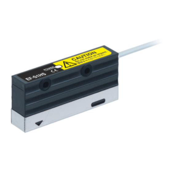
Peel off the protective seal from the measuring part in the sensor head (EF-S1HS).
Preparation
①
Connect the sensor head and the controller.
②
Mount the sensor head at a distance of 8 to 20.5mm from the object to be measured (if
③
the measured value is anticipated to be 1,000V or less) or 21 to 100mm (if the
measured value is anticipated to exceed 1,000V). (Note 1)
Notes: 1) The metal parts of sensor head are connected to the 0V line of the controller power supply, so it
should be insulated during use.
④ T urn on the power. (The software version will be displayed for approximately 3 seconds.)
T urning on the power
⑤ Set the distance that the sensor head was mounted at in step
Distance setting
③.
For details on the setting method, refer to '
the instruction manual for the controller.
The factory setting for the distance is 8mm. If you are using
the sensor head at a distance of 8mm, then the setting does
not need to be changed.
⑥ Set the threshold value for judgment output.
Threshold value setting
For details on the setting method and setting ranges, refer to '
(The factory setting is ±100.)
⑦ Carry out 0-Adjust after measuring the metal plate that is
0-Adjust
connected to the ground.
For details on the setting method, refer to '
the instruction manual for the controller.
⑧ When R UN mode is started, measurement can start. (Note 2)
Start measurement
Notes: 2) A 10-minute warming-up period is needed after the power is turned on, so carry out the 0-Adjust operation if accuracy is required.
2
FOR GREATER MEASUREMENT ACCURACY
● It is recommended that you carry out the following operations in order to improve measurement accuracy during use.
Measurement range
・ This product measures electric fields. Because of this, if any objects are present inside the measurement area (refer to
the illustration at right) or near the sensor head which might disturb the electric field around the object being
measured, it will affect measurement accuracy.
(
The shorter the measurement distance, the more difficult it will be for nearby objects to have an adverse effect on
measurement.
In order to obtain the most accurate measurement results, mount the sensor head while taking into account factors
such as the measurement distance, measurement area and ambient environment.
Using together with an ionizer
・ If the sensor head is installed near a device such as an ionizer which generates a large fluctuating magnetic field, the measurement values may become unstable. In such cases,
mount the sensor head as far away from the ionizer as possible, or change the settings by delaying the response time so that measurement will be more stable.
For details on setting the response time, refer to '
9
PRO MODE / PRO1 mode setting' in the instruction manual for the controller.
Calibration
・ If the potential of the object being measured is already known, the measurement value for the sensor head can be set to the value that is already-known.
This can help to cancel out any errors arising from measurement conditions and measurement range errors after the sensor head has actually been mounted, so that more
accurate measurement can be carried out.
For details, refer to '
9
PRO MODE / PRO1 mode setting' in the instruction manual for the controller.
Protective
seal
Setting distance range
8 to 100mm
<Reference>
The sensor output will vary depending on the measurement distance for the
7
NAVI MODE' in
sensor head.
Correction is carried out based on the measurement distance, so use the
controller to set the measurement distance, and used at that fixed distance.
The measurement range will change as shown in the table below depending on
whether the measurement distance is 8 to 20.5mm or 21 to 100mm.
Measurement distance (mm)
Measurement range
8 to 20.5
-1,000 to +1,000 (±1kV range)
21 to 100
-1,999 to +1,999 (±2kV range)
6
R UN MODE' and '
8
SETTING RANGE' in the instruction manual for the controller.
<Reference>
Carrying out 0-Adjust allows the measurement value baseline to be set to the
6
R UN MODE' in
value that is currently being measured.
The factory setting is for the measurement value baseline potential to be set to
0V , but it is possible for there to be some difference between that and the
enclosure ground. Be sure to carry out 0-Adjust in order to ensure that stable
sensing can be carried out.
Measurement distance - Measurement area (typical)
8
)
10
20
40
3
JUDGMENT OUTPUT
The output mode (window comparator mode / 2-output mode) and output status
●
(normal open / normal close) can be set for both OUT1 and OUT2.
For details on the setting method, refer to '
●
in the instruction manual for the controller.
<Window comparator mode + Normal open>
OUT1 turns ON when the measurement value is at or above the + threshold value, or at
●
or below the - threshold value.
OUT2 turns ON when an over-range result ('
●
For normal close, the output logic is reversed.
●
Notes: 1) An over-range result is generated in the following cases:
・When the potential of the object being measured is outside the specification range for the
sensor head
・When analog output is 5V or more, or 1V or less
Object being
measured
<2-output mode + Normal open>
If the measurement value is at or above the + threshold value, OUT1 turns ON.
●
If the measurement value is at or below the - threshold value, OUT2 turns ON.
●
For normal close, the output logic is reversed.
●
<Hysteresis>
・ The hysteresis can be set to one of five levels in order to prevent chattering. The factory setting for hysteresis is 20. For details on the setting method, refer to '
PRO1 mode setting' in the instruction manual for the controller.
<Normal open>
ON
OFF
(- potential) - threshold value
4
EXTERNAL INPUT OPERATIONS AND HOLD MEASUREMENT
If HOLD mode is set to '
●
be carried out using the timing input signal or the jog switch.
・When timing input is ON or the jog switch is turned (to the '+' or '-' side):
Peak hold measurement
During peak hold measurement, the + peak value and the - peak value are updated
●
while timing signal input is being received, and these values are held until the next
signal is input.
The timing input signal should be input for 2ms or more.
●
OUT1 and OUT2 output a judgment signal depending on the peak hold values, but
●
hold operation is not carried out for analog output.
The hysteresis function does not work during judgment output.
φ23
φ30
φ112
φ200
Measurement area (mm)
5
ANALOG OUTPUT
The relationship between measurement values and analog
●
output for the sensor head is shown in the illustration at right.
Analog output can have its focus set to x2, x5 or x10. (The
●
factory setting is for no focus.)
<Points to note when using analog output>
Because the 0V lines for judgment output and analog output are
common, the analog output may vary depending on the load
current.
In order to satisfy the linearity specifications for the analog output,
do not use the judgment output.
Output operation timing chart
+ potential
display
9
PRO MODE / PRO6 mode setting'
+ threshold
value
- threshold
value
- potential
' o r '
') is generated. (Note 1)
display
Window comparator mode + Normal open
・
OUT1
2-output mode + Normal open
・
OUT1
OUT2
Notes:
<Normal close>
Hysteresis
Hysteresis
ON
OFF
(0)
+ threshold value (+ potential)
Output operation timing chart
', '
' or '
', the peak hold measurement can
Timing
input
+ potential
display
+ threshold
value
- threshold
value
- potential
display
OUT1
OUT2
For ±1kV range: +1,000
For ±2kV range: +1,999
For ±1kV range: -1,000
For ±2kV range: -1,999
Panasonic Industry Co., Ltd.
1006, Oaza Kadoma, Kadoma-shi, Osaka 571-8506, Japan
https://industry.panasonic.com/
Please visit our website for inquiries and about our sales network.
Panasonic Industry Co., Ltd. 2024
April, 2024
0
2) The threshold values can be set separately for + potentials and - potentials.
PRO MODE /
9
Hysteresis
Hysteresis
(- potential) - threshold value
(0)
+ threshold value (+ potential)
0
0
Full-scale (F .S.)
For ±1kV range: -1,000
0
For ±1kV range: +1,000
For ±2kV range: -1,999
For ±2kV range: +1,999
Potential (V)
PRINTED IN JAPAN
Hysteresis
Hysteresis
ON
OFF
ON
OFF
ON
OFF
ON
OFF
ON
OFF
ON
OFF
5
3
1
Advertisement

Related Manuals for Panasonic EF-S1 Series


Summary of Contents for Panasonic EF-S1 Series
- Page 1 ● display (normal open / normal close) can be set for both OUT1 and OUT2. When using the EF-S1 series of electrostatic sensors for the first time Hysteresis For details on the setting method, refer to ' PRO MODE / PRO6 mode setting' ●...
- Page 2 示 グ PR Oモードについて・PR O1モード設定」をご参照ください。 詳細については、コントローラの取扱説明書「 れています) 値 出 力 <アナログ出力使用時の注意事項> 判定出力とアナログ出力の0Vが共通のため、負荷電流に ±1kVレンジの場合:-1,000 フルスケール(F .S.) よってアナログ出力が変動する場合があります。 ±2kVレンジの場合:-1,999 アナログ出力の直線性仕様を満足するためには、判定出 ±1kVレンジの場合:-1,000 ±1kVレンジの場合:+1,000 力を使用しないでください。 ±2kVレンジの場合:-1,999 ±2kVレンジの場合:+1,999 電位(V) パナソニック インダストリー株式会社 〒571-8506 大阪府門真市大字門真1006番地 https://industry.panasonic.com/ <FAデバイス技術相談窓口> TEL:0120-394-205 受付時間:平日の9時~12時、13時~17時(土日祝日、年末年始、当社休業日を除く) Panasonic Industry Co., Ltd. 2024 2024年4月発行 PRINTED IN JAPAN...
Need help?
Do you have a question about the EF-S1 Series and is the answer not in the manual?
Questions and answers