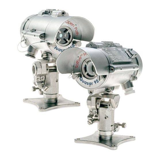
Spectrex SafEye Quasar 950 Quick Start Manual
Open path toxic gas detectors
Hide thumbs
Also See for SafEye Quasar 950:
- User and maintenance manual (72 pages) ,
- Manual (64 pages) ,
- Manual supplement (2 pages)

Related Manuals for Spectrex SafEye Quasar 950


Summary of Contents for Spectrex SafEye Quasar 950
- Page 1 Quick Start Guide 00925-0100-4036, Rev AA February 2024 SafEye Quasar 950/960 ™ Open Path Toxic Gas Detectors...
- Page 2 Each component is represented by a number representing a discrete quantization. Digital signal processing Electromagnetic compatibility Electromagnetic interference HART Highway addressable remote transducer communication ® protocol Immune at any distance IECEx International Electrochemical Commission explosion Internet protocol Refers to the three infrared sensors Spectrex.net...
-
Page 3: Table Of Contents
February 2024 Quick Start Guide Abbreviation Meaning Light-emitting diode Liquefied natural gas MilliAmps (0.001 amps) Modbus Master-slave messaging structure ® Not applicable National pipe thread NTSC National Television System Committee (a color encoding system) Phase alternation by line (a color encoding system) Part number Concentration in parts per million. - Page 4 Quick Start Guide February 2024 Spectrex.net...
-
Page 5: Installation Instructions
February 2024 Quick Start Guide 1 Installation instructions 1.1 General considerations 1.1.1 Personnel Only employ suitably qualified personnel who are familiar with the local codes and practices and trained for gas detection maintenance. Ensure that wiring is only performed and supervised by someone with knowledge of electronics and, in particular, wiring installation. - Page 6 Quick Start Guide February 2024 1.1.3 Site requirements When installing the SafEye Quasar 950/960, take into account the weight of the monitored gas compared to that of the surrounding air and the individual site requirements. Ensure that the site selected gives the receiver a direct view to the transmitter.
- Page 7 February 2024 Quick Start Guide relevant separation distance between the neighboring OPGD systems according to the installation lengths as listed in Table 1-2. Table 1-2: Minimum Separation Distances Installation line of sight distance Minimum separation 33 ft. (10 m) 3.3 ft. (1 m) 66 ft.
- Page 8 • Function check filter: for H S/S0 or NH Other accessories are available, per customer request: • Pole mount (U-bolt 5-in.) • Pole mount (U-bolt 2–3-in.) • RS-485 harness kit • HART hand-held harness kit ® • Protective cover Spectrex.net...
- Page 9 February 2024 Quick Start Guide 1.2.2 Required tools Install the device using the following general purpose common tools and equipment. Table 1-3: Tools Tool Function Alignment kit Provides tools to install fine alignment tool. Hex key 8 mm Mounts the detector on the tilt mount. Hex key 3/16-in.
- Page 10 6.51 V 6.51 V 6.51 V 68.5 mA 68.5 mA 68.5 mA 68.5 mA 68.5 mA 68.5 mA 689.5 111.5 111.5 111.5 111.5 111.5 111.5 111.5 0 μF 0 μF 0 μF 0 μF 0 μF 0 μF 0 μF Spectrex.net...
- Page 11 February 2024 Quick Start Guide Paramet Channels LED 1 LED 2 HART RS485+ RS485- ® connecti combine 0 μH 0 μH 0 μH 0 μH 0 μH 0 μH 0 μH 22 μF 22 μF 22 μF 22 μF 22 μF 22 μF 22 μF 7.5 mH...
- Page 12 3. Where Um marked on the associated apparatus is less than 250 V, it shall be installed in accordance with one of the following: Spectrex.net...
- Page 13 February 2024 Quick Start Guide • Where Um does not exceed 50 Vac or 120 Vdc, in a SELV or PELV system or • Via a safety isolating transformer complying with the requirements of CAN/CSA-C22.2 No. 66.1 or technically equivalent standard or •...
- Page 14 • Ex marking: Class I Zone 1 AEx eb IIC Gb, Zone 21 AEx tb IIIC Db • Temperature rating: -67 °F (-55 °C) to 182 °F (83 °C) or better Spectrex.net...
- Page 15 February 2024 Quick Start Guide • Connecting thread: M25 x 1.5 or ¾-in. NPT 6. Equipment is only to be installed by manufacturer trained personnel. 7. Equipment has only been tested for electrical safety. No evaluation of functional safety and performance characteristics has been conducted.
- Page 16 Figure 1-2: Mounting the tilt mount and detector using the lower mounting access A. Front shield B. Back cover C. Security screw D. Locating pins E. Alternate mounting location Spectrex.net...
- Page 17 February 2024 Quick Start Guide Figure 1-3: Tilt mount A. Tilt mount holding plate B. Transmitter or receiver holding plate C. Vertical crude alignment tightening screw D. Vertical fine alignment tightening screw E. Horizontal fine alignment tightening screw F. Horizontal crude alignment tightening screw G.
- Page 18 Procedure 1. Place the tilt mount holding plate in its designated location and secure it with four fasteners through four holes with diameters of 0.3-in. (8.5 mm). Spectrex.net...
- Page 19 February 2024 Quick Start Guide NOTICE Skip this step if the tilt mount is already installed. Removing the receiver for maintenance purposes does not require removing the tilt mount. 2. Place the receiver with its conduit/cable inlets pointing downwards on the receiver holding plate of the tilt mount. 3.
- Page 20 C. Earth terminal D. Inlet conduit E. Internal earth connection F. Connection to handheld unit G. Receiver holding plate 2. Remove the protective plug mounted on the detector conduit/ cable entry inlet. 3. Pull the wires through the detector inlet conduit. Spectrex.net...
- Page 21 February 2024 Quick Start Guide 4. Use a ¾-in. - 14 NPT or M25 x 1.5 conduit connection/cable gland to assemble the cable conduit to the detector. 5. Connect the wires to the required terminals according to the wiring diagrams. 6. Connect the grounding wire to the ground screw outside the detector.
- Page 22 1. Release the back screw bolt and open the source back cover. The chamber is now exposed. Figure 1-6: Source with cover removed A. Housing B. Terminal board C. Earth terminal D. Inlet conduit E. Internal earth connection F. Transmitter holding plate Spectrex.net...
- Page 23 February 2024 Quick Start Guide 2. Remove the protective plug mounted on the source conduit/ cable entry inlet and pull the wires through the source inlet. Use a ¾-in. - 14 NPT or M25 x 1.5 conduit connection/cable gland to assemble the cable/explosion-proof conduit to the detector.
- Page 24 Support the receiver when loosening the vertical lock screws. 5. Approximately aim the transmitter vertically towards the receiver. 6. Tighten the outer vertical lock screw. 7. Repeat this process for the receiver. Spectrex.net...
- Page 25 February 2024 Quick Start Guide 1.9.2 Perform fine alignment Refer to Figure 1-4 to see the receiver with the alignment tool installed. Procedure 1. Remove the front shield and mount the alignment tool on the front of the transmitter using the three screws. The alignment tool is supplied in the commissioning kit.
-
Page 26: Operation
2. Ensure that the 4–20 mA wiring meter is connected to the receiver. 3. Power up the system 18 to 32 Vdc. After sixty seconds, the current meter indicates 4 mA. Postrequisites After powering up, zero calibrate the system. Spectrex.net... - Page 27 February 2024 Quick Start Guide 2.3 Verify signal Use an RS-485 or HART Field Communicator to verify the signal in ® accordance with Table Figure 2-1: Light-Emitting Diode (LED) Indication Before Zero Calibration 1. Verify LED indication. 2. Use Winhost or HART to verify installation parameters. 2.3.1 ...
- Page 28 D. Maximum range E. Reference minimum F. Signal minimum G. Ratio H. NQ ratio 2.4 Zero calibrate Prerequisites Zero calibrate after any of the following: • Installation • Realignment • Window cleaning • Any change in receiver or transmitter position Spectrex.net...
- Page 29 February 2024 Quick Start Guide Prerequisites WARNING Only zero calibrate when: • No combustible gases are present. • There is a clear path between the transmitter and receiver. • Weather conditions are clear. Before zero-calibrating, align the detector precisely. Quick Start Guide...
- Page 30 Prerequisites To switch from each position (Step 1 through Step 3), use either WinHost, HART , or RS-485 or move the magnetic mode selector ® above the magnetic switch (see Figure 2-4). Procedure 1. Switch from Normal to Alignment mode. Spectrex.net...
- Page 31 February 2024 Quick Start Guide 2. Switch from Alignment to Standby mode. 3. Switch from Standby to Zero Calibration mode. The 0–20 mA output should now be at 1 mA. 4. Wait up to sixty seconds until it switches to Normal mode. The receiver reading is now set to Normal.
-
Page 32: Product Certifications
Quick Start Guide February 2024 3 Product certifications 3.1 ATEX, IECEx The SafEye Quasar 950/960 is approved per ATEX and IECEx certifications: • ATEX Ex II 2(2)G D Ex db eb ib [ib Gb] IIB+H T4 Gb Ex tb [ib Db] IIIC T135 °C Db •... - Page 33 February 2024 Quick Start Guide ABNT NBR IEC 60079-11 ABNT NBR IEC 60079-28 ABNT NBR IEC 60079-31 Marking: Ex db eb ib [ib Gb] IIB+H T4 Gb Ex tb [ib Db] IIIC T135 °C Db (–55 °C ≤ Ta ≤ +65 °C) Certificate No: UL-BR 16.1063X (Rosemount) and UL-BR 22.4058X (Spectronix).
- Page 34 Quick Start Guide February 2024 The Quasar 950/960 is a "Class 1 Laser Product" per IEC 60825-1: 2014 ed. 05. Spectrex.net...
-
Page 35: Wiring Configurations
February 2024 Quick Start Guide A Wiring configurations Figure A-1: Receiver wiring terminal A. Power (+) 18 to 32 Vdc B. Return (-) C. 0-20 mA (input) D. 0-20 mA (output) E. RS-485 (+) F. RS-485 (-) G. Ground Quick Start Guide... - Page 36 Quick Start Guide February 2024 Figure A-2: Transmitter wiring terminal A. Power (+) 18 to 32 Vdc B. Return (-) C. Not used D. Not used E. Not used F. Ground Spectrex.net...
- Page 37 February 2024 Quick Start Guide Figure A-3: 0-20 mA Sink 4 Wire A. Receiver B. Controller C. Input power: 18-32 Vdc D. Return E. 0-20 mA meter Quick Start Guide...
- Page 38 Figure A-4: 0-20 mA Non-Isolated Sink 3 Wire A. Receiver B. Controller C. Input power: 18-32 Vdc D. Return E. 0-20 mA meter Figure A-5: 0-20 mA Source 3 Wire A. Receiver B. Controller C. Input power: 18-32 Vdc D. Return E. 0-20 mA meter Spectrex.net...
- Page 39 Quick Start Guide A.1 RS-485 communication network Using the RS-485 network capability of the SafEye Quasar 950/960 detector and additional software, it is possible to connect up to 32 receivers in an addressable system with four wires only (two for power and two for communication).
- Page 40 Quick Start Guide February 2024 Spectrex.net...
-
Page 41: Declaration Of Conformity
February 2024 Quick Start Guide B Declaration of conformity Quick Start Guide... - Page 42 Quick Start Guide February 2024 Spectrex.net...
- Page 43 February 2024 Quick Start Guide Quick Start Guide...
- Page 44 *00925-0100-4036* Quick Start Guide 00925-0100-4036, Rev. AA February 2024 For more information: Emerson.com/global © 2024 Emerson. All rights reserved. Emerson Terms and Conditions of Sale are available upon request. The Emerson logo is a trademark and service mark of Emerson Electric Co. Rosemount is a mark of one of the Emerson family of companies.
Need help?
Do you have a question about the SafEye Quasar 950 and is the answer not in the manual?
Questions and answers