Table of Contents
Advertisement
Quick Links
Advertisement
Table of Contents

Related Manuals for Spectrex SafEye Xenon 700S

Summary of Contents for Spectrex SafEye Xenon 700S
- Page 1 IECEx Approved Ex d e ia [ia Ga] IIC T5 Gb Document Ref: TM 799200, Rev. (4) April 2017 8200 Market Blvd, Chanhassen, MN 55317, USA Phone: +1 (973) 239 8398 Fax: +1 (973) 239 7614 Website: www.spectrex.net; Email: spectrex@spectrex.net...
- Page 2 This page intentionally left blank...
-
Page 3: Legal Notice
Legal Notice The SPECTREX SafEye Gas Detector described in this document is the property of Rosemount. No part of the hardware, software or documentation may be reproduced, transmitted, transcribed, stored in a retrieval system or translated into any language or computer language, in any form or by any means, without prior written permission of Rosemount. -
Page 4: Release History
Release History Date Revision History Prepared by Approved by June 2011 First Release Ian Buchanan Eric Zinn August 2013 Second Release Ian Buchanan Eric Zinn January 2014 Third Release Ian Buchanan Eric Zinn April 2017 Fourth Release Jay Cooley Shaul Serero... -
Page 5: Table Of Contents
Table of Contents Xenon 700S Open-Path Gas Detection System ..........i Legal Notice ....................iii Release History ....................iv About this Guide ..................... 13 Abbreviations and Acronyms ................14 Scope ....................... 15 Product Overview .................. 15 Technical Description ................17 Features .................... - Page 6 2.6.2 Detector Unit .................. 27 Operating Modes..................29 Operational Modes ................29 3.1.1 Normal Mode .................. 29 3.1.2 Maintenance Call Mode (3mA Output) ..........30 3.1.3 Fault Mode ..................30 3.1.4 Zero Calibration Mode (1mA Output) ..........30 Output Signals ..................31 3.2.1 Standard 0–20mA Current Output .............
- Page 7 4.4.4 Salt and Fog ................... 41 4.4.5 Water and Dust ................41 4.4.6 Shock and Vibration ................ 42 4.4.7 Electromagnetic Compatibility (EMC): ..........42 Installation Instructions ................43 Introduction ..................43 General Considerations ................43 5.2.1 Personnel ..................43 5.2.2 Tools Required................
- Page 8 Safety Precautions ................57 Signal Verification ................. 57 6.5.1 Signal Values Limitation ..............58 Zero Calibration ..................58 Functional Check ................... 60 Maintenance Instructions ................ 61 General Maintenance ................61 Periodic Maintenance ................61 7.2.1 Routine Optical Surface Cleaning ............62 7.2.2 Signal Verification ................
- Page 9 C.10 Mini Laptop Kit ..................75 Appendix D: SIL-2 Features ..............77 Safety Relevant Parameters ..............77 Guidelines for Configuration, Installation, Operation, and Maintenance ..77 D.2.1 Conditions for Safe Operation ............77 D.2.2 Alarm Operation Using the 0–20mA Signal Current ......78 D.2.3 Relay Outputs ................
- Page 10 List of Figures Figure 1: Wiring Options ..................24 Figure 2: Flash Source Unit ................26 Figure 3: Detector Unit ..................28 Figure 4: Tilt Mount ................... 49 Figure 5: Detector and Tilt Mount Assembly ............50 Figure 6: Detector with Cover Removed ............... 51 Figure 7: Source with Cover Removed ..............
- Page 11 List of Tables Table 1: Gas Concentrations Measurement Terms ..........18 Table 2: Gas Calibrations ................... 20 Table 3: Model Numbers and Installation Distances ..........22 Table 4: Detector Types ..................27 Table 5: Standard (Default) 0–20mA Current for the Gas Channel ......31 Table 6: Optional - Discrete Reading of 0–20mA at Different Detector Modes ....
-
Page 13: About This Guide
About this Guide This manual describes the SafEyeTM Xenon 700S Gas Detection System and its features and provides instructions on how to install, operate, and maintain the detector. This guide includes the following chapters and appendices: Chapter 1, Scope, provides a general introduction and overview of the product and the guide, with a brief description of its content. -
Page 14: Abbreviations And Acronyms
Abbreviations and Acronyms Abbreviation Meaning American Wire Gauge Built In Test Electromagnetic Compatibility End of Line Field of View HART Highway Addressable Remote Transducer- communication protocol Immune at Any Distance IECEx International Electrotechnical Commission Explosion Isopropyl Alcohol Infrared Jet Fuel Latched Refers to relays remaining in the ON state even after the ON condition has been removed... -
Page 15: Scope
The programmable functions are available through an RS-485 port used with host software supplied by SPECTREX, and a standard PC or an I.S. handheld unit. The SafEye Source and Detector unit enclosures are IECEx certified Exd... -
Page 17: Technical Description
Technical Description In this chapter… Features page 17 Applications page 18 Principles of Operation page 18 Product Marking page 22 Models and Types page 22 Description page 25 Features Long range gas detection up to 459ft/140m Simultaneous detection of C1–C8 flammable gases ... -
Page 18: Applications
Principles of Operation Applications The SafEye Xenon system may be used to monitor flammable gas concentration in various applications, such as: Petrochemical, pharmaceutical, and other chemical storage and production areas Flammable and toxic chemical storage sites, and hazardous waste disposal areas ... -
Page 19: Spectral Finger Print
Principles of Operation 2.3.2 Spectral Finger Print Each hazardous material is detected at a specific wavelength selected according to its specific spectral absorption or “finger print.” There are 3 IR sensors: 2 signals and 1 reference. The detection process involves 2 separate filters, one transmitting radiation that is absorbed by a particular gas, and one that is not sensitive to it. -
Page 20: Gas And Mixture Selection And Setting
Actual selections should be made by the user in consultation with experts to provide for safety requirements. However, for special cases where none of the 4 calibrations are appropriate, SPECTREX, through its local agents, can advise how to calibrate a SafEye Detector to any specific gas. -
Page 21: Heated Optics
Principles of Operation 2.3.8 Heated Optics SafEye Xenon includes heated optics for the detector and source. To improve performance in conditions where there is ice, condensation, or snow, the heater increases the temperature of the optical surface by 5–8°F / 3–5°C above the ambient temperature. The heated optics are configured to automatically operate when the change in temperature requires heating (default). -
Page 22: Tilt Mount
Models and Types 2.3.11 Tilt Mount The newly designed stainless steel tilt mount provides a smaller installation footprint that can conform to limited space constraints, while the sturdy construction maintains alignment even with constant vibration. The improved “X” and “Y” axis worm-gear adjustments provide quick and easy alignment for installation and maintenance procedures. - Page 23 Models and Types The 700S Series has 3 wiring options: Option 1: Power, alarm relay, fault relay, 0–20mA Option 2: Power, alarm relay, fault relay, accessory relay Option 3: Power, alarm relay, RS-485, 0–20mA, RS-485 RTN (default) Note: SIL2 covers only 0–20mA outputs.
-
Page 24: Figure 1: Wiring Options
Models and Types Figure 1: Wiring Options SafEye Xenon 700S Gas Detector User Guide... -
Page 25: Description
Description Description The SafEye is comprised of 2 main units: The Flash Source Unit The Detector Unit Xenon 700S detects gases over an open path transmitted from the flash source to the detector. 2.6.1 Flash Source Unit The flash source unit emits IR radiation pulses at the rate of 2 pulses per second. -
Page 26: Figure 2: Flash Source Unit
Description Main Housing Telescope Site Junction Box Back Cover Earth Terminal Cable Inlet Front Window/Lens Section Holding Plate Figure 2: Flash Source Unit SafEye Xenon 700S Gas Detector User Guide... -
Page 27: Detector Unit
Description 2.6.2 Detector Unit The detector receives the transmitted pulsed radiation signals from the flash source. The signals are then amplified and fed into an analog-to-digital signal converter to be processed by the internal microprocessor. When the signals drop below a prescribed level, the internal microprocessor will compensate for them. -
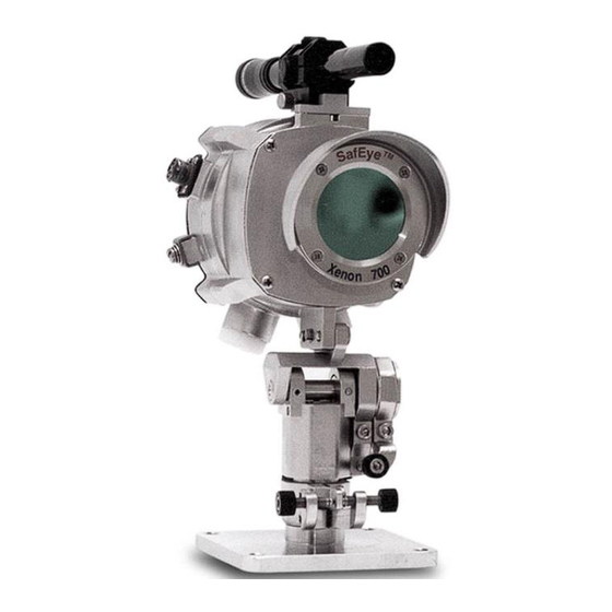
Page 28: Figure 3: Detector Unit
Description Main Housing Telescope Site Junction Box Handheld Fast Connection Back Cover Earth Terminal Cable Inlet Front Window/Window Section Holding Plate Figure 3: Detector Unit SafEye Xenon 700S Gas Detector User Guide... -
Page 29: Operating Modes
Operating Modes In this chapter… Operational Modes page 29 Output Signals page 31 System Setup page 33 Operational Modes The SafEye 700S has 4 operational modes: Normal Mode Maintenance Call Mode (3mA Output) Fault Mode Zero Calibration Mode (1mA Output) 3.1.1 Normal Mode This mode is used for gas detection. -
Page 30: Maintenance Call Mode (3Ma Output)
Operational Modes 3.1.2 Maintenance Call Mode (3mA Output) This mode indicates a low signal or low signal ratio that may be caused by a dirty window, misalignment, poor source, or that 1 of the detector’s parameters is at the “limit” value. The detector continues to operate, reading any gas present, but provides a (3mA) pre-warning signal that a maintenance procedure is required. -
Page 31: Output Signals
Output Signals Output Signals The SafEye system provides the following outputs depending upon the wiring option selected (see Models and Types, page 22): Standard 0–20mA Current Output Dry Contact Relays RS-485 Interface 3.2.1 Standard 0–20mA Current Output The 0–20mA output can provide the detector status measurement in one of the following ways: ... -
Page 32: Dry Contact Relays
Output Signals Table 6: Optional - Discrete Reading of 0–20mA at Different Detector Modes LEL.m Current Reading Status and Description Setting 0+0.3mA Fault 2 or Low Voltage 1±0.3mA Zero Calibration 2±0.3mA Fault 1 3±0.3mA “Maintenance Call” 4±0.5mA Standby 14±0.5mA Warning 19±0.5mA Alarm 21mA... -
Page 33: System Setup
System Setup System Setup The customer can define various system settings, as described in the following sections. 3.3.1 Detection Function Programming The SafEye 700S series incorporates several functions that can be set by the customer, using: The HART handheld unit (P/N 799810). Refer to Manual TM 799060 for programming instructions. -
Page 34: Table 7: Sensitivity Levels Options
System Setup 3.3.2.2 Full Scale Two full scales are available: Table 7: Sensitivity Levels Options Sensitivity Full Scale Warning Level Alarm Level Normal 5 LEL.m 1 LEL.m 3 LEL.m High 2 LEL.m 0.4 LEL.m 1 LEL.m When choosing a full scale, the warning and alarm levels will change automatically according to the table. -
Page 35: Default Detector Setup
System Setup 3.3.2.6 Heated Optic Operation The heated optics for the detector unit can be defined as 1 of the following modes: Off – Not operated On – Operated continuously Auto – On, per temperature change (default) When the detector is set “per temperature change,”... -
Page 36: Table 10: Source Default Setup
System Setup Table 10: Source Default Setup Function Setting Heat mode Auto Heat on The source default can be changed only at the factory. SafEye Xenon 700S Gas Detector User Guide... -
Page 37: Technical Specifications
Technical Specifications In this chapter… General Specifications page 37 Electrical Specifications page 38 Mechanical Specifications page 40 Error! Not a valid result for table. page 41 General Specifications Detected Gases: Simultaneous detection of C1–C8 flammable gases Detection Distance range: Table 11 Table 11: Detection Distance Range Min. -
Page 38: Electrical Specifications
Electrical Specifications Response Time: 3sec to T90 Spectral Response: 3.0–4.0 micron Sensitivity Range: 0–5 LEL.m 0–2 LEL.m Field of View: Line of Sight Alignment Tolerance: ± 1° Drift: Long term ± 5% of full scale Temperature Range: -40°F/-40°C to +131°F/+55°C Immunity to false alarm: Does not produce a false alarm and is not influenced by solar radiation, hydrocarbon... -
Page 39: Electrical Outputs
The protocol enables continuous communication between a single standard Modbus controller (master device) and a serial network of up to 247 detectors. The protocol enables connections between different types of SPECTREX detectors or other Modbus devices to the same network. 4.2.4.3 Relay Output The detector may include up to 3 of the following relays depending on the wiring configuration selected. -
Page 40: Mechanical Specifications
Mechanical Specifications 4.2.4.4 HART Protocol The HART Protocol is a digital communication signal at low levels in addition to the 0–20mA. This a bi-directional field communications protocol used to communicate between intelligent field instruments and the host system. Through the HART Protocol the detector can: ... -
Page 41: Environmental Specifications
Environmental Specifications Environmental Specifications The SafEye system is designed to withstand harsh environmental conditions. The source and detector units compensate for adverse conditions while maintaining accuracy. 4.4.1 High Temperature Designed to meet MIL-STD-810C, Method 501.1 Procedure II Operating Temperature: +131ºF/+55ºC Storage Temperature: +149ºF/+65ºC 4.4.2... -
Page 42: Shock And Vibration
Environmental Specifications 4.4.6 Shock and Vibration Vibration: Designed to meet MIL-STD-810C, Method 514.2, Procedure VIII Mechanical Shock: Designed to meet MIL-STD-810C, Method 516.1, Procedure I 4.4.7 Electromagnetic Compatibility (EMC): This product is in conformance with EMC directive 89/336/EC. Radiated Emission: EN61000-6-3 Conducted Emission: EN61000-6-3... -
Page 43: Installation Instructions
Installation Instructions In this chapter… Introduction page 43 General Considerations page 43 Preparations for Installation page 45 Conduit/Cable Installation page 46 Detector/Source Mounting page 46 Detector Wiring page 48 Detector Terminal Wiring page 52 Flash Source Wiring page 53 Introduction The detector and flash source units can be installed and maintained using general-purpose common tools and equipment. -
Page 44: Tools Required
General Considerations 5.2.2 Tools Required The SafEye system requires the following tools: Set of screwdrivers Set of hex keys/Allan wrenches (supplied with commissioning kit) Voltage Multimeter 5.2.3 Site Requirements When selecting a site location and position for the SafEye system, the following points must be considered: ... -
Page 45: Tips For Selecting A Gas Detector Location
Preparations for Installation 5.2.5 Tips for Selecting a Gas Detector Location The following are some tips for selecting gas detector locations, in order to provide the best detection coverage: For heavier-than-air gases: below potential leak sources. For lighter-than-air gases: above potential leak sources. ... -
Page 46: Preparing For Installation
Detector/Source Mounting 5.3.1 Preparing for Installation To prepare for installation of the 700S Gas Detector: Verify the appropriate purchase order. Record the part number (P/N) and serial number of the detectors and source units and the installation date in an appropriate log book. Open the container package immediately prior to detector installation, and visually inspect the detectors, sources, and accessories. -
Page 47: Tilt Kit
Detector/Source Mounting 5.5.1 Tilt Kit The following contents are included with the tilt mount kit P/N 799640): Table 14: Tilt Mount Kit Item Type/Model Tilt Mount 799220 Screw 5/16” – 18 UNC x 3/4” Spring Washer No. 5/16” 5.5.2 Detector/Source Installation (Figure 4 and Figure 5) ... -
Page 48: Detector Wiring
Detector Wiring Detector Wiring (Figure 5 and Figure 6) To install the detector wiring: Remove the 4 socket-head-screws (Item 14, Figure 5) that secure the detector back cover (Item 15, Figure 4). The chamber is now exposed. Remove the protective plug mounted on the detector conduit/cable entry inlet and pull the wires through the detector inlet (Item 4, Figure 6). -
Page 49: Figure 4: Tilt Mount
Detector Wiring Figure 4: Tilt Mount Table 15: Tilt Mount Description Vertical Fine Alignment Tilt Mount Holding Plate Tightening Screw Detector/Source Holding Vertical Crude Alignment Plate Tightening Screw Horizontal Crude Alignment Vertical Fine Alignment Screw Tightening Screw Horizontal Fine Alignment Horizontal Fine Alignment Tightening Screw Screw... -
Page 50: Figure 5: Detector And Tilt Mount Assembly
Detector Wiring Figure 5: Detector and Tilt Mount Assembly Table 16: Detector and Tilt Mount Assembly Description Tilt Mount Holding Plate Detector Tightening Screw Detector/Source Holding Detector Tightening Washer Plate Horizontal Crude Alignment Detector Tightening Screw Horizontal Fine Alignment Telescope Tightening Screw Vertical Fine Alignment Telescope Tightening Bolt... -
Page 51: Figure 6: Detector With Cover Removed
Detector Wiring Figure 6: Detector with Cover Removed Table 17: Detector with Cover Removed Description Housing Internal Earth Connection Terminal Board Connection to Handheld Unit Earth Terminal Detector Holding Plate Inlet Conduit Detector Telescope Site TM 799200 Rev. (4), April 2017... -
Page 52: Detector Terminal Wiring
Detector Terminal Wiring Detector Terminal Wiring The detector has 3 output wiring options in the rear, segregated, “Exde” terminal section, with 9 Terminals, labeled 1–9. Option 3 is the default unless otherwise specified at the time of the order. The following describes the function of each electrical terminal of the detectors for all wiring options: Table 18: Wiring Options Terminal Number... -
Page 53: Flash Source Wiring
Flash Source Wiring Flash Source Wiring 5.8.1 Wiring To install the wiring: Remove the 4 socket-head-screws (Item 14, Figure 5) that secure the source back cover (Item 15, Figure 5). The chamber is now exposed. Remove the protective plug mounted on the source conduit/cable entry inlet;... -
Page 54: Figure 7: Source With Cover Removed
Flash Source Wiring Figure 7: Source with Cover Removed Table 19: Source with Cover Removed Description Housing Internal Earth Connection Terminal Board Earth Terminal Detector Holding Plate Inlet Conduit Detector Telescope Site SafEye Xenon 700S Gas Detector User Guide... -
Page 55: Operating Instructions
Operating Instructions In this chapter… SafEye Operation page 55 Alignment of Unit page 55 Powering Up the System page 57 Safety Precautions page 57 Signal Verification page 57 Zero Calibration page 58 Functional Check page 60 SafEye Operation Once the system is in place, it automatically monitors for the specified gases, and sends signals to a standard control panel or PC. -
Page 56: Alignment Of Unit
Alignment of Unit Notes: To ensure proper alignment according to factory calibration, prior to telescope installation, verify that the telescope and its sight mounting are free of dirt. To ensure optimal alignment, do not attempt to change factory calibration of the telescope or its mounting. -
Page 57: Powering Up The System
External devices such as automatic extinguishing systems must be disconnected before performing maintenance tasks required by the warranty. Signal Verification Perform signal verification through the host software supplied by SPECTREX (see Detection Function Programming, page 33). TM 799200, Rev. (4), April 2017... -
Page 58: Signal Values Limitation
Zero Calibration 6.5.1 Signal Values Limitation Table 20 describes the maintenance data channels limitation values. Table 20: Maintenance Channels Limited Values Installation Distance Channel Maintenance Reference 1V Gain1 1V Gain2 The minimum signal Gain3 allowed is 2.5V at Gain 4 Signal 1 1V Gain1 1V Gain2... -
Page 59: Figure 8: Magnetic Mode Selector
Zero Calibration To perform the zero calibration procedure: Switch from normal to alignment mode indication. Switch from alignment to standby mode. Switch from standby to zero calibration mode. The 0–20mA output should now be at 1mA. Wait up to 60 seconds until the mode switches to normal. The detector reading is now set to normal and the 0–20mA output indicates 4mA. -
Page 60: Functional Check
Functional Check Functional Check The SafEye system has been calibrated at the factory for the user's specific gas or vapor detection requirements. The functional check procedure validates the system’s functional operation. The functional check filter is a convenient operational check used to confirm that response has not changed from previous readings. -
Page 61: Maintenance Instructions
Maintenance Instructions In this chapter… General Maintenance page 61 Periodic Maintenance page 61 General Maintenance Only basic periodic maintenance is required to keep the SafEye Xenon 700 at maximum performance and reliability levels. The detector and source units can be maintained with the use of common tools and equipment. The test results should be recorded in a maintenance logbook, together with a copy of the delivery form. -
Page 62: Routine Optical Surface Cleaning
Periodic Maintenance 7.2.1 Routine Optical Surface Cleaning The SafEye system, being an optical device, must be kept as clean as possible. The optical surfaces involved are the source and detector viewing windows. To clean the optical windows: Disconnect the power to the SafEye detector and source. In places where dust or dirt has accumulated on the optical surface, clean the surface with a small, soft-bristle brush. -
Page 63: Troubleshooting
Troubleshooting In this chapter… Troubleshooting Problems page 63 Troubleshooting Problems Table 21: Troubleshooting Problems Problem Cause Solution “Maintenance call” Poor alignment Perform alignment status or R, S1, and Dirt on the Clean the window S2 are below 2.5VDC window at Gain 4 Poor light source Replace the light source Detector fault... -
Page 65: Appendix A: Wire Selection Tables
Appendix A: Wire Selection Tables In this appendix… General Instructions for Electrical Wiring page 65 General Instructions for Electrical Wiring Refer to Table 22 to determine the required wire gauge for general wiring, such as relay wiring. Calculate the permitted voltage fall with respect to loads current, wire gauge, and length of wires. -
Page 66: Table 23: Wiring Length In Feet/Meters
General Instructions for Electrical Wiring Table 23: Wiring Length in Feet/Meters No. of Recommended Wire Diameter Power Supply Range Detectors (VDC) 22–32 22–32 22–32 20–32 20–32 4 and less 20–32 meters Max. Length from power supply to last detector SafEye Xenon 700S Gas Detector User Guide... -
Page 67: Appendix B: Wiring Option Configurations
Appendix B: Wiring Option Configurations In this appendix… RS-485 page 71 Figure 9: Wiring Option 1 Note: Only 0–20mA is SIL2 approved. TM 799200 Rev. (4), April 2017... -
Page 68: Figure 10: Wiring Option 2
Wiring Option Configurations Figure 10: Wiring Option 2 Note: This option does not comply with SIL2 requirements. SafEye Xenon 700S Gas Detector User Guide... -
Page 69: Figure 11: Wiring Option 3 (Default)
Wiring Option Configurations Figure 11: Wiring Option 3 (Default) Note: Only 0–20mA is SIL2 approved. Figure 12: 0–20mA Wiring (Sink) For Wiring Options 1 and 3 TM 799200 Rev. (4), April 2017... -
Page 70: Figure 13: 0-20Ma Wiring (Source) For Wiring Options 1 And 3
Wiring Option Configurations Figure 13: 0–20mA Wiring (Source) For Wiring Options 1 and 3 Notes: The detectors are factory set to isolated 0–20mA-sink version. For non-isolated 0–20mA version (source), connect Terminal 8 to Terminal 1. The 0–20mA meter is connected between Terminal 7 and Terminal 2. -
Page 71: Rs-485 Communications Network
RS-485 Communications Network RS-485 Communications Network By using the RS-485 network capability of the SafEye Xenon 700S Detector and additional software, it is possible to connect up to 32 detectors in an addressable system with 4 wires only (2 for power and 2 for communication). -
Page 73: Appendix C: Accessories
Appendix C: Accessories In this appendix… Tilt Mount page 73 Pole Mount (U-Bolt 4–5”) page 73 Pole Mount (U-Bolt 2–3”) page 73 Wall Mount page 73 HART Handheld Diagnostic Unit page 74 USB/RS-485 Harness Converter Kit page 74 Commissioning Kit page 74 Weather Cover for the Source Unit page 74... -
Page 74: Hart Handheld Diagnostic Unit
USB/RS-485 Harness Converter Kit The USB RS-485 Harness Kit with RS-485/USB converter (P/N 794079), together with SPECTREX host software, enables the user to connect to any available PC or laptop to reconfigure settings or perform diagnostics on the XENON 700 Gas Detector. -
Page 75: Mini Laptop Kit
Mini Laptop Kit C.10 Mini Laptop Kit The mini laptop (P/N 777820), pre-loaded with SPECTREX software, enables setting reconfiguration or diagnostics performance on all flame and gas detectors in the series. Refer to Manual TM777070 for programming instructions when using the mini laptop kit. -
Page 77: Appendix D: Sil-2 Features
Appendix D: SIL-2 Features In this appendix… Safety Relevant Parameters page 77 Guidelines for Configuration, Installation, page 77 Operation, and Maintenance Miscellaneous page 78 This appendix details the special conditions for compliance with the requirements of EN 61508 for SIL-2. The SafEye 700S can be used in low and high demand mode applications, see IEC 61508.4, Chapter 3.5.12. -
Page 78: Alarm Operation Using The 0-20Ma Signal Current
Miscellaneous D.2.2 Alarm Operation Using the 0–20mA Signal Current The connected controller monitors the 0–20mA signal current for valid values. (See Output Signals, page 31). Mode Normal Warning Alarm Continuous current 4mA/0 LEL.m 7.2mA/1 13.6mA/3 with low sensitivity LEL.m LEL.m (Full Scale: 5 LEL.m) Continuous current 4mA/0 LEL.m... - Page 79 This page intentionally left blank...
-
Page 80: Technical Support
Phone: +1 (973) 239 8398 Fax: +1 (973) 239 7614 Email: spectrex@spectrex.net Website: www.spectrex.net Your Local SPECTREX Office: Texas (USA) Mr. Jay Cooley, Regional Sales Manager: 16203 Park Row, Suite 150 Houston, Texas 77084 Phone: +1 (832) 321 5229 Email: jay.cooley@emerson.com...
Need help?
Do you have a question about the SafEye Xenon 700S and is the answer not in the manual?
Questions and answers