
Related Manuals for Husqvarna 598 46 31-01


Summary of Contents for Husqvarna 598 46 31-01
- Page 1 INSTALLATION AND REPAIR PARTS MANUAL 42 INCH (107 CM) REPLACEMENT MOW ER DECK FOR LAWN TRACTORS PART NUMBER 598 46 31-01 598 46 34-01...
-
Page 2: Safety Rules
SAFETY RULES Safe Operation Practices for Ride-On Mowers DANGER: THIS CUTTING MACHINE IS CAPABLE OF AMPUTATING HANDS AND FEET AND THROW ING OBJECTS. FAILURE TO OBSERVE THE FOLLOWING SAFETY INSTRUCTIONS COULD RESULT IN SERIOUS INJURY OR DEATH. • Never leave a running machine unattended. Always turn WARNING: In order to prevent ac ci den tal off blades, set parking brake, stop engine, and remove starting when setting up, trans port ing,... - Page 3 SAFETY RULES Safe Operation Practices for Ride-On Mowers III. CHILDREN • If fuel is spilled on clothing, change clothing immediately. • Never overfill fuel tank. Replace gas cap and tighten securely. WARNING. CHILDREN CAN BE INJURED BY THIS EQUIPMENT. The American Academy GENERAL SERVICE of Pediatrics recommends that children be a •...
-
Page 4: Removal And Installation
REMOVAL & INSTALLATION WARNING: TO AVOID SERIOUS INJURY, BEFORE PERFORMING ANY SER VICE OR AD JUST MENTS: • Depress brake pedal fully and set parking brake. • Ensure transaxle is in the neutral position. • Place attachment clutch in “DISENGAGED” position. •... - Page 5 REMOVAL & INSTALLATION • ATTACH MOWER SIDE SUSPENSION ARMS (A) TO • ATTACH FRONT LINK (E) - Work from left side of trac- CHASSIS - Position hole in arm over pin (B) on outside tor. Insert rod end of link assembly through front hole of tractor chassis and secure with retainer spring.
- Page 6 TO LEVEL MOWER TO LEVEL MOWER • If adjustment is necessary, see step in Visual Adjust- ment instructions above. Make sure tires are properly inflated to the PSI shown on • Recheck measurements, adjust if necessary until both tires. If tires are over or under inflated, it may affect the sides are equal.
- Page 7 SERVICE NOTES...
-
Page 8: Repair Parts
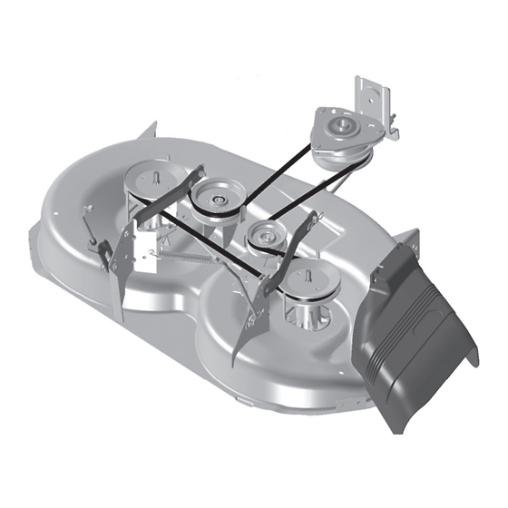
REPAIR PARTS 42 INCH (107 CM) REPLACEMENT MOWER DECK PART NUMBER 598 46 31-01... - Page 9 REPAIR PARTS 42 INCH (107 CM) REPLACEMENT MOWER DECK PART NUMBER 598 46 31-01 PART PART DESCRIPTION DESCRIPTION 532 43 98-17 Mower Deck Assembly, 42" 532 40 47-84 Bracket, Wheel Guage, LH 539 99 03-16 RHSNB 5/16-18 x 3/4 Gr. 5...
- Page 10 SERVICE NOTES...
- Page 11 SERVICE NOTES...
- Page 12 08.12.19 CL Printed in the U.S.A.
Need help?
Do you have a question about the 598 46 31-01 and is the answer not in the manual?
Questions and answers