Table of Contents
Advertisement
Quick Links
RANSOMES
Safety and Operation Manual
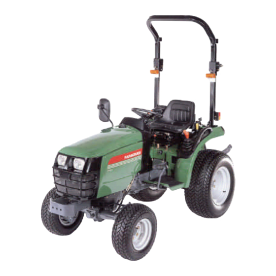
TT Tractors
Series: TT318 / TT321 / TT324
WARNING: If incorrectly used this machine can cause se-
vere injury. Those who use and maintain this machine should
be trained in its proper use, warned of its dangers and should
read the entire manual before attempting to set up, operate,
adjust or service the machine.
GB
(RJ 100 042000)
®
RANSOMES
Part No. 24336G (rev.0)
Advertisement
Table of Contents

Related Manuals for Textron Ransomes TT318 Series


Summary of Contents for Textron Ransomes TT318 Series
- Page 1 RANSOMES ® Safety and Operation Manual TT Tractors Series: TT318 / TT321 / TT324 WARNING: If incorrectly used this machine can cause se- vere injury. Those who use and maintain this machine should be trained in its proper use, warned of its dangers and should read the entire manual before attempting to set up, operate, RANSOMES adjust or service the machine.
- Page 2 The electro-magnetic field generated by the add-on system should not exceed 24V/m at any time and at any location in the proximity of electronic components. Failure to comply with these rules will render the RANSOMES warranty null and void. © 2000, Textron Inc. All Rights Reserved...
-
Page 3: General Information
GENERAL INFORMATION PLEASE READ CAREFULLY: For a complete list of the pre-delivery service checks performed by your dealer, refer to the PRE-DELIVERY SERVICE check list found at the back of this manual. Keep one copy as your record of the service performed. -
Page 4: Table Of Contents
CONTENTS GENERAL INFORMATION....................................1 INTERNATIONAL SYMBOLS...................................3 SAFETY PRECAUTIONS..................................CONTROLS, INSTRUMENTS AND OPERATION.........................8 - 29 SEAT, SEAT BELT AND ROPS................................8 - 9 LIGHTING...........................................10 INSTRUMENT PANEL, KEY SWITCH............................11 - 12 STARTING THE ENGINE....................................12 STOPPING THE ENGINE....................................13 BREAK-IN PROCEDURES..................................13 THROTTLE CONTROLS.....................................14 BRAKE CONTROLS......................................15 TRANSMISSION, FOUR-WHEEL DRIVE AND PTO......................16 - 20 FOUR-WHEEL DRIVE....................................16 MECHANICAL TRANSMISSION..............................16 - 17 HYDROSTATIC TRANSMISSION ...............................17 - 18... -
Page 5: International Symbols
INTERNATIONAL SYMBOLS As a guide to the operation of your tractor, various international symbols have been utilized on the instruments and controls. The symbols are shown below with an indication of their meaning. Engine Speed Glow Control Lever Operating Direction Hours Recorded Engine Stop Rock Shaft... - Page 6 SAFETY PRECAUTIONS The following precautions are suggested to help prevent accident PERSONAL SAFETY SAFETY AND THE TRACTOR Throughout this manual and on machine decals, you will find precau- tionary statements ( “CAUTION”, ”WARNNG”, and “DANGER”) fol- Read the Operator’s Manual carefully before using the tractor. lowed by specific instructions.
- Page 7 SAFETY PRECAUTIONS The following precautions are suggested to help prevent accident • Dust waste should be dampened, placed in a sealed container Keep the tractor and equipment, particularly brakes and the steering, maintained in a reliable and satisfactory condition to and marked to ensure safe disposal.
- Page 8 SAFETY PRECAUTIONS The following precautions are suggested to help prevent accident nect safety in case of accidental detachment of implement. 11. When operating stationary PTO driven equipment, always 12. Do not leave equipment in the raised position. place both gear shift levers in neutral, apply the tractor parking brake and block the rear wheels front and back.
-
Page 9: Safety Precautions
SAFETY PRECAUTIONS The following precautions are suggested to help prevent accident DIESEL FUEL SAFETY FRAME (ROPS) Under no circumstances should gasoline, alcohol or blended If your RANSOMES Tractor is equipped with a safety frame it must fuels be added to diesel fuel. These combinations can create be maintained in a serviceable condition. -
Page 10: Controls, Instruments And Operation
CONTROLS, INSTRUMENTS AND OPERATIONS SEAT, SEAT BELT AND ROPS Replace the seat belt if it becomes damaged or worn. Seat Adjustment Two seat belt brackets have been provided, one Your RANSOMES Tractor is equipped with an adjustable suspension seat as shown in Figure 1. each fender, to hang each end of the seat belt from when it is not I use. - Page 11 CONTROLS, INSTRUMENTS AND OPERATIONS ROLLOVER PROTECTIVE STRUCTURE (ROPS) Your tractor is equipped with a folding Roll Over Protective Structure (ROPS). ROPS are effective in reducing injuries during tractor overturn accidents. Overturning tractor without a ROPS can result in serious injury or death.
-
Page 12: Lighting
CONTROLS, INSTRUMENTS AND OPERATIONS LIGHTING hazard function, move the hazard flasher switch, clockwise to activate all four indicator lights. HAZARD FLASHER WARNING LIGHTS AND Depressing the center button will sound the horn. COMBINATION SWITCH Your RANSOMES tractor is equipped with hazard light, Figure 7. -
Page 13: Instrument Panel, Key Switch
CONTROLS, INSTRUMENTS AND OPERATIONS INSTRUMENT PANEL RPM. Use the proof meter as a guide to determine hourly service maintenance intervals. Tachometer- Registers engine (Revolutions Per Minute). The gauge is marked in increments of 100 and will return to zero when the engine is not running. High Beam Indicator - Illuminates when the headlights are switched to main beam. -
Page 14: Starting The Engine
CONTROLS, INSTRUMENTS AND OPERATIONS KEY SWITCH the cold start indicator light has gone out, the glow plugs will continue to heat if the key is held in the The key switch is shown in Figure 11. “HEAT position. WARNING: Do not use ether with the Turning the key to the right to the “ON”... -
Page 15: Stopping The Engine
CONTROLS, INSTRUMENTS AND OPERATIONS BREAK-IN PROCEDURES 1. Shield eyes. 2. Connect one end of the jumper cable to the Your RANSOMES Tractor will provide long and tractor battery positive ( ) terminal and the dependable service if given proper care during the other to the auxiliary battery positive ( ) 50 hour break-in period. -
Page 16: Throttle Controls
CONTROLS, INSTRUMENTS AND OPERATIONS THROTTLE CONTROLS ELECTRICAL SOCKET for Traile r A standard seven-pin socket, Figure 12, is provided HAND THROTTLE AND ENGINE STOP CONTROL mounted on the left side of the tractor at the rear. The hand throttle is shown in Figure 13. Push the With reference to the picture inset, the socket connections (as viewed from the rear of the tractor) throttle rearward to increase engine rpm. -
Page 17: Brake Controls
CONTROLS, INSTRUMENTS AND OPERATIONS BRAKE CONTROLS PARKING BRAKE CONTROL The parking brake, shown in Figure 16, is used for BRAKE PEDALS locking the brake pedals in the applied position. The brake pedals are shown in Figure 15. The right The parking brake should be applied whenever the brake pedal is used to brake the right rear wheel. -
Page 18: Transmission, Four-Wheel Drive And Pto
CONTROLS, INSTRUMENTS AND OPERATIONS FOUR-WHEEL DRIVE around the gearshift lever. Three forward and one reverse speeds are The shift lever for the four-wheel drive is located provided for each of the two ranges. This provides on the right-hand of the seat, Figure 18. a total of 6 forward and 2 reverse speeds. -
Page 19: Hydrostatic Transmission
CONTROLS, INSTRUMENTS AND OPERATIONS SPEED RANGE MAIN Figure 22 - H.S.T. Foot Pedal Figure 21 - Speed Range Combinations,9 × H.S.T. Range Selector Lever The range selector lever is located oh the left-hand control pod, Figure 23. It has two speed ranges and one neutral position. -
Page 20: Clutch Pedal
CONTROLS, INSTRUMENTS AND OPERATIONS H.S.T. Cruise Control The H.S.T. Cruise Control switch is located on the right-hand side of the console and is used to remain a constant forward speed, Figure 24. NOTE: Cruise control will not function in the reverse direction. -
Page 21: Pto Controls And Operation
CONTROLS, INSTRUMENTS AND OPERATIONS The differential lock is engaged by depressing the POWER TAKE-OFF pedal located on the right side of the rear axle center housing tractor with mechanical The power take-off (PTO) in your tractor transfers transmission, Figure 26. engine power directly to PTO equipment. -
Page 22: Towing The Tractor
CONTROLS, INSTRUMENTS AND OPERATIONS POWER TAKE-OFF OPERATION position. 8. Disconnect the P.T.O.-driven shaft at the tractor WARNING: To reduce the possibility of PTO shaft before traveling on highways or for personal injury comply with any great distance. following before attaching or detaching 9. -
Page 23: Hood Lutch
CONTROLS, INSTRUMENTS AND OPERATIONS HOOD LATCH THREE POINT LINKAGE As viewed from the front of the tractor. The tractor’s standard three-point linkage is used to attach fully mounted equipment to the rear of the 1. To raise the hood, move the latch lever j, to tractor. -
Page 24: Hydraulic Lift System
CONTROLS, INSTRUMENTS AND OPERATIONS HYDURAULIC LIFT SYSTEM When operating in position control, there is a Hydraulic Power Lift (HPL) definite relationship between the position of the control lever in the quadrant and the position of the The hydraulic Power lift (H.P.L.) is located on the equipment. - Page 25 CONTROLS, INSTRUMENTS AND OPERATIONS To operate auxiliary equipment, remove the plugs from the manifold block and connect the feed hose to the outlet port, Figure 37and the return hose to the inlet port. Figure 35 - Linkage Adjustment FLOW CONTROL VALVE The flow control valve, Figure 36, provides an adjustment to regulate the flow of oil from the lift Figure 37 - Hydraulic Manifold Block...
- Page 26 CONTROLS, INSTRUMENTS AND OPERATIONS AUXILIARY SERVICE CONTROL (ASC) VALVE On the single spool valve, pull the control lever rearward to extend the cylinder. Push the control lever forward to retract the cylinder. Release the To operate the ASC valve, remove the position control lever, shown in Figure 40, to the to of the control lever to stop the cylinder in any position before it is fully extended.
- Page 27 CONTROLS, INSTRUMENTS AND OPERATIONS TWO-SPOOL CONTROL VALVE (OPTIONAL ) The optional two-spool control valve is mounted on the right side of the clutch housing beside the engine hood. This valve is used mainly for front end loader operation, but may also be used to operate other front-mounted implements.
-
Page 28: Driving The Tractor
CONTROLS, INSTRUMENTS AND OPERATIONS DRIVING THE TRACTOR l Any towed vehicle whose total weight exceeds WARNING Observe following that of the towing tractor must be equipped precautions when driving the tractor. with brakes for safe operation. l Always check overhead clearance, especially l Watch where you are going especially at row when transporting the tractor. -
Page 29: Wheel Tread Settings
CONTROLS, INSTRUMENTS AND OPERATIONS WHEEL TREAD SETTINGS NOTE: Tread settings are measured from center of tyre to center of tyre. Rear Wheel Settings Front Wheel Settings Front Tyre Type Tread Setting Note Rear Tyre Type Tread Setting Note Agricultural 820 mm Adjustable Agricultural 851-999 mm... -
Page 30: Tractor Weighting
CONTROLS, INSTRUMENTS AND OPERATIONS TRACTOR WEIGHTING Front-mounted equipment varies in weight. Refer to equipment manual for ballsting. WARNING: If proper stability cannot obtain sufficient traction maximum performance in heavy draft operations and to obtained within weighting counter-balance rear-mounted equipment, weight limitations below, reduce the load should be added to the tractor in the form of liquid... -
Page 31: Tire Pressures
CONTROLS, INSTRUMENTS AND OPERATIONS LIQUID BALLAST (OPTIONAL) Rear Wheel Weights It is a common practice to add weight to the tractor Location Weight(s) by filling the rear tyres with liquid. A calcium Maximum of 4 weights chloride (CaCl water solution Rear wheel per tractor @ recommended due to its low freezing point and... -
Page 32: Lubrication And Maintenance
LUBRICATION AND MAINTENANCE LUBRICATION AND MAINTENANCE CHART RANSOMES ST318, ST321, ST324 FOUR-WHEEL DRIVE... -
Page 33: Fuel And Lubricants
LUBRICATION AND MAINTENANCE FUEL AND LUBRICANTS l When filling the tank, maintain control of the nozzle. l Don’t fill the fuel tank to capacity...allow room DIESEL FUEL for expansion. Type of fuel to use : l Wipe up spills immediately When operating in temperatures above -6.7°C (20°F), use diesel fuel oil No.2 - D with a minimum l Always tighten the fuel tank cap securely. - Page 34 LUBRICATION AND MAINTENANCE REFUELING THE TRACTOR the hood in the fully raised position. 2. To lower the hood, lift up on the hood slightly The fuel filler cap is located at the rear of the trac- and pull the support link towards you, so that tor hood.
-
Page 35: Fuel And Lubricant Service Procedures
LUBRICATION AND MAINTENANCE LUBRICANTS IMPORTANT: Engine crankcase oil drain intervals should be adjusted downward when diesel fuel Type of lubricant to use, sulfur content is over 0.5%. Transmission, Rear Axle, Final Consult your dealer for details of Engine Crank Reduction, and Hydraulic System SAE 80 case Oil usage. - Page 36 LUBRICATION AND MAINTENANCE 1. With the engine off, but at normal operating temperature, drain and discard the engine oil by removing the drain plug, Figure 51. Reinstall the plug after the oil has drained and discard the oil. 2. Unscrew the oil filter, Figure 49, catching the used oil in a suitable container placed below the filter.
- Page 37 LUBRICATION AND MAINTENANCE WARNING: Fuel oil in the injection 1. Be sure there is adequate fuel in the fuel tank, close the fuel shut-off valve, then remove the system is under high pressure and can fuel sediment bowl, Figure 52. penetrate the skin.
- Page 38 LUBRICATION AND MAINTENANCE 5. Loosen the injector line fittings at the injectors. 3. after cleaning the element, check the inner di- ameter seals for damage. If damage is present, 6. Move the hand throttle control lever to its wide replace the primary element. open position.
- Page 39 LUBRICATION AND MAINTENANCE TRANSMISSION, REAR AXLE AND Changing Oil: Change the oil every 300 hours. HYDRAULIC SYSTEM 1. With the oil at normal operating temperature, Checking Oil Level: Check the oil level every 50 drain and discard the oil by removing the trans- hours.
-
Page 40: General Maintenance
LUBRICATION AND MAINTENANCE HYDRAULIC SYSTEM OIL FILTER cation Chart, page 30 )require the application of a good quality grease every 50 hours. In extremely The hydraulic system is equipped with a spin-on dirty conditions, lubrication should be more often. type oil filter, Figure 57. Replace the filter after the Refer to page 33 for the type of grease that should first 50 hours of operation and every 300 hours be used. - Page 41 LUBRICATION AND MAINTENANCE drain radiator and engine block, Figure 59. by the radiator cap. It is dangerous to remove the cap while the system is hot. Always cover the cap with a thick cloth and turn the cap slowly counter- clockwise to the first stop.
- Page 42 LUBRICATION AND MAINTENANCE 4. Clean the radiator cap and cap seal. Install the water outlet connection so that the heat ele- cap. ment(spring end)will be in the cylinder head of the engine. 5. Clean the radiator front screen, Figure 60. 6.
- Page 43 LUBRICATION AND MAINTENANCE FUEL INJECTOR REMOVAL AND tings at the injectors until after bleeding the fuel INSTALLATION system. Tighten the fittings at the injection pump and injectors to 78-83 N. m.(58 - 61 lbs. ft.). The injectors should be cleaned, tested, and ad- 3.
- Page 44 LUBRICATION AND MAINTENANCE the adjusting screw at the push rod end of the valve rocker arm either into or out of the arm while checking for correct clearance with the feeler gauge. 4. Install the rocker arm cover. Use a new gasket if the old one is damaged.
- Page 45 LUBRICATION AND MAINTENANCE MAINTENANCE AND INSPECTION OF After an accident, check for damage to (1) the THE ROPS ROPS, (2) the operator’s seat, (3) the seat belt and the seat belt mountings. Before you operate the NOTE: Inspect the ROPS after the first 20 hours of machine, replace all damaged parts.
- Page 46 LUBRICATION AND MAINTENANCE BATTERY ALTERNATOR Keep the battery connections tight and free of cor- The alternator, Figure 70, is belt-driven from the rosion. An ammonia or baking soda-water solution is good for washing the outside surface and termi- engine crankshaft pulley. It is important that belt nals of the battery.
- Page 47 LUBRICATION AND MAINTENANCE Upper Fuse Block - Figure 71 and that the negative terminal is connected to ground. Reverse polarity will destroy the Fuse Size Circuit Protected rectifier diodes in the alternator. 20 amp. Headlights, Parking lights If the charge indicator warning light indicates Instrument panel lights that the alternator is not charging the battery, 15 amp.
- Page 48 LUBRICATION AND MAINTENANCE IMPORTANT: Always replace the fusible link wire TAIL LAMP AND FLASHER WARNING LIGHTS with the appropriat fusible link wire for this tractor. To replace a tail lamp bulb or flasher warning light bulb : 1. Remove the lens, then remove the bulb. 2.
- Page 49 LUBRICATION AND MAINTENANCE TIRES Inflation and Service l Upon receiving your tractor, check the air pres- reposition tire on rim, relubricate both tire sure in the tires as indicated in the tables. beads and rim flanges and re-inflate. Inflation beyond 35 psi with-unseated beads may break l Check tire pressure every 50 hours, or weekly.
- Page 50 LUBRICATION AND MAINTENANCE FOOT- BRAKE ADJUSTMENT FRONT WHEEL TOE-IN Front wheel toe-in adjustments on your tractor Whenever the brake pedal travel becomes exces- were made at the factory. Normally, the wheels sive, or if the travel of one pedal is unequal to that maintain their toe-in ;...
- Page 51 LUBRICATION AND MAINTENANCE HANDBRAKE ADJUSTMENT CLUTCH PEDAL ADJUSTMENT Adjustment of the handbrake should be carried To obtain maximum clutch life, it is essential that out after the foot brakes have been adjusted. the clutch pedal free travel be checked every 50 hours so as to maintain free travel at 19-30 mm(3/4-1-3/16 inches ), Figure 80.
- Page 52 LUBRICATION AND MAINTENANCE FOUR-WHEEL DRIVE the type specified, page FRONT AXLE DIFFERENTIAL CASE AND FINAL REDUCTION GEAR CASES Checking Oil Level: Check the oil level every 50 hours. 3. With the tractor standing level and the engine off, check the oil level with the dipstick, Figure 4.
-
Page 53: Tractor Storage
LUBRICATION AND MAINTENANCE TRACTOR STORAGE Tractors that are to be stored for an extended pe- riod should be protected during storage. The fol- IMPORTANT: Do not use No.2 diesel fuel for win- lowing is a suggested list of operations to be car- ried out. - Page 54 LUBRICATION AND MAINTENANCE Tractor that have been placed in storage should be completely serviced in the following manner before using : 1. Inflate the tires to the recommended pressures, and remove the blocking. 2. Check the oil level in the engine crankcase, the common sump (for the hydraulic lift, transmis- sion, rear axle and optional power steering), and optional front wheel drive axle.
-
Page 55: General Torque Specification Table
LUBRICATION AND MAINTENANCE... -
Page 56: Specifications
SPECFICATIONS ENGINE COOLING SYSTEM-Cont’d. Type .............Diesel Number of Cylinders......3 Water Pump: Type ..........Centrifugal Tractor ST318 9x3 ST321 9x3 Drive..........V-Belt Model ST318HST ST321HST ST324HST Water Pump Belt Engine Deflection ....10-15 mm (7/16 to 9/16) Model S753 S773 S773L when 9-11 kg (20-25 lbs.) 75 mm 77 mm 77 mm... - Page 57 SPECFICATIONS STEERING TYRES Type ......... Power Front: Turns Lock-to-Lock....2.5 AG......ST318 9x3 : 5-12, R1, 4Ply Front Wheel Toe-In....0-5 mm ST321/324 9x3 : 6-12, ..........(0-13/64 in.) R1, 4Ply Turning Radius TURF ......ST318/321/324 HST : (Without Brake) ....2180 mm 8.00-10, R3, 4Ply ×...
- Page 58 SPECFICATIONS GENERAL DIMENSIONS ST318 ST321 ST324 (79.5 in.) Transmission Tire Size Front AG 5-12 20x8.00-10 AG 6-12 20x8.00-10 20x8.00-10 Rear AG 8-16 29x12.00-15 AG 9.5-16 29x12.00-15 29x12.00-15 Overall Length 2728 mm 2728 mm 2728 mm Length 2728 (With 3-point Hitch) (107.4 in.) (107.4 in.) (107.4 in.)
-
Page 59: Safety And Instruction Decals
SAFETY DECALS In the event that decals become damaged or illegible, they should be replaced with new decals at their original position. Replacement decals are available from your RANSOMES Tractor Dealer. WARNING - BATTERY PART NO. - 490992480 LOCATION - Front side of battery Batteries produce explosive gas. - Page 60 INSTRUCTION DECALS PTO Control Lever MID PTO Control Lever PART NO.- 390171940 PART NO.- 390171950 LOCATION - Top of L.H. LOCATION - Top of L.H. fender fender Differential Lock PART NO.- 390191690 LOCATION - Above pedal below seat Starter Switch PART NO.- 390197280 LOCATION - Right side of instrument panel...
- Page 61 INSTRUCTION DECALS Position Control and Four-wheel Drive Control PART NO. - 390372430 LOCATION - Top of R.H. fender Flow Control Knob PART NO. - 390370290 LOCATION - Top of flow control knob Rear Remote Control PART NO. - 390370300 LOCATION - Right & below seat Engine Oil Ground Speed Diagram - 9x3 PART NO.
- Page 62 INSTRUCTION DECALS NOTES...
-
Page 63: Predelivery And 50-Hour Service
PRE-DELIVERY SERVICE CHECK AND ADJUST AS REQUIRED INOPERATIVE SERVICE CHECKS OPERATIVE SERVICE CHECKS 15. Front wheel toe-i n ....................1. Ti r e pressure......................16. Fuel l e vel ........................2. Ai r cl e aner el e ment 17. - Page 65 PRE-DELIVERY SERVICE CHECK AND ADJUST AS REQUIRED OPERATIVE SERVICE CHECKS 15. Front wheel toe-i n ....................INOPERATIVE SERVICE CHECKS 16. Fuel l e vel ........................17. Sheet metal and pai n t condi t i o n..............Al l operati n g checks are to be performed wi t h the tractor at normal 1.
- Page 68 World Class Quality, Performance and Support Equipment from Textron Turf Care and Specialty Products is built to exacting standards ensured by ISO 9001 registration at all our manufacturing locations. A worldwide dealer network and factory-trained technicians backed by Textron Parts Xpress provide reliable, high-quality product support.
Need help?
Do you have a question about the Ransomes TT318 Series and is the answer not in the manual?
Questions and answers