
Subscribe to Our Youtube Channel
Related Manuals for Textron Ransomes CT435


Summary of Contents for Textron Ransomes CT435
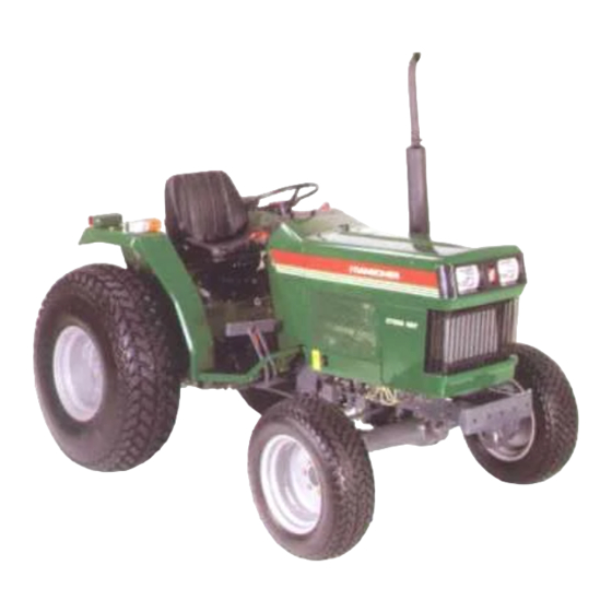
- Page 1 CT435 COMPACT TRACTOR OPERATORS INSTRUCTIONS RANSOMES Ransomes Way, Ipswich, England, IP3 9QG Publication No. 24080G (rev.1) (RSJ 001 101997)
- Page 3 PLEASE READ CAREFULLY: For a complete list of the pre-delivery service checks performed by your dealer, refer to PRE-DELIVERY SERVICE on the upper portion of page 61 and 63. The copy on page 61 is your record of the service performed, and the copy on page 63, which is to be removed from the manual, is your dealer’s.
-
Page 4: Table Of Contents
CONTENTS INTERNATIONAL SYMBOLS .................. 3 SAFETY PRECAUTIONS ..................4-5 CONTROLS AND INSTRUMENTS ............... 6-13 SEAT AND ROPS ....................6 LIGHTING ........................ 7 INSTRUMENT PANEL ................... 7-9 THROTTLE CONTROLS ..................9 BRAKE CONTROLS ....................10 DIFFERENTIAL CONTROL ..................10 TRANSMISSION AND PTO CONTROLS ............10-12 HYDRAULIC LIFT SYSTEM CONTROLS ............ -
Page 5: International Symbols
INTERNATIONAL SYMBOLS As a guide to the operation of your tractor, various international symbols have been utilised on the instruments and controls. The symbols are shown below with an indication of their meaning. Glow Engine speed Control lever operating direction Engine stop Hours recorded Rock shaft... -
Page 6: Safety Precautions
SAFETY PRECAUTIONS The following precautions are suggested to help prevent accidents. A careful operator is the best operator. Most accidents can be pressurising lines. avoided by observing certain precautions. Read and take the following precautions before operating this tractor to help prevent If fluid is injected into the skin, obtain medical attention accidents. - Page 7 SAFETY PRECAUTIONS SAFETY PRECAUTIONS (Continued) To avoid injury, do not clean, adjust, unclog or service P.T.O. If the front end of the tractor tends to rise when heavy driven equipment when the tractor engine is running. implements are attached to the three-point hitch, install front end or front wheel weights.
-
Page 8: Controls And Instruments
CONTROLS AND INSTRUMENTS SEAT AND ROPS assembly. If the ROPS was deleted by the original purchaser or has been removed, it is recommended TRACTOR SEAT that you equip your tractor with a Roll Over Your RANSOMES Tractor is equipped with a Protective Structure (ROPS). -
Page 9: Lighting
CONTROLS AND INSTRUMENTS LIGHTING INSTRUMENT PANEL FLASHER WARNING LAMP KEY SWITCH Your RANSOMES tractor is equipped with flasher The key switch is shown in Figure 5. Turning the warning lights, Figure 3. The switch, Figure 4 for the ‘key to the left will activate the cold-start aid. warning lights is located on the instrument panel. - Page 10 CONTROLS AND INSTRUMENTS that it points straight up and down. To close the fuel FUEL GAUGE shutoff valve, move the handle to the horizontal The fuel gauge is shown in Figure 5 and 6. The position. Always shut off the valve ‘A/hen servicing needle indicates the amount of fuel in the tank.
-
Page 11: Throttle Controls
CONTROLS AND INSTRUMENTS • The hours and portions of hours your tractor has operated, based on an average engine speed of 1867 rpm. Engine speeds below 1 867 rpm accumulate engine hours at a slower rate than clock hours. Engine speeds above 1 867 rpm accumulate engine hours faster than clock hours. -
Page 12: Brake Controls
CONTROLS AND INSTRUMENTS BRAKE CONTROLS DIFFERENTIAL CONTROL BRAKE PEDALS DIFFERENTIAL LOCK PEDAL The brake pedals are shown in Figure 9. The right The differential lock pedal is shown in Figure 10. brake pedal is used to brake the right rear wheel. Depressing the pedal locks the rear axle shafts The left pedal is used to brake the left rear wheel. - Page 13 CONTROLS AND INSTRUMENTS Figure 11. A diagram showing the shift pattern is CREEPER RANGE (ACCESSORY) shown on the bezel around the gear shift lever. A creeper range accessory with a 1 2.29 : 1 ratio is Range selector is located at the left-hand side of the available which provides an additional 1 2 forward seat, Figure 11.
-
Page 14: Hydraulic Lift System Controls
CONTROLS AND INSTRUMENTS during uses such as loader operation, that do not require use of the P. T. 0. system. WARNING: The P. T. 0. system cannot be disengaged with the alternate clutch pedal stop. DO NOT engage the alternate STOP with the P. T. 0. control lever in the on position. - Page 15 CONTROLS AND INSTRUMENTS the seat. To lower the lift arms, push the lever DRAFT AND POSITION CONTROL LEVERS forward. The adjustable stop is provided for (OPTIONAL) returning the lever to a preset position in the The hydraulic lift control levers are shown in Figure quadrant.
-
Page 16: Operation
OPERATION BREAK-IN PROCEDURES WARM WEATHER STARTING Your RANSOMES Tractor will provide long and To start a cold engine in warm weather or to start an dependable service if given proper care during the engine that is warm: 50 hour break-in period During the first 50 hours of Depress the clutch pedal fully and move the operation. -
Page 17: Stopping The Engine
OPERATION IMPORTANT: In cold weather below 23°F (-5°C) • Follow the battery manufacturer’s instructions start the engine after holding the key switch to the which are shown on the battery “HEAT” position for approximately 10 seconds even if the glow plug indicator warning light has gone out. WARNING: Do not use ether with the STOPPING THE ENGINE themostat starting aid. - Page 18 OPERATION Figure 23 - Speed Range Combinations (12 X 12) Synchromesh Transmission) IMPORTANT: When shifting down on the go, shift through each gear sequence. Skipping gears while down shifting can damage components due to over Figure 22 - Speed Range Combinations (12 x 4 speed.
- Page 19 OPERATION IMPORTANT: Avoid using the clutch pedal as a “footrest” (riding the clutch). Prolonged operation in this manner can cause damage to the clutch components. FOUR-WHEEL DRIVE The four-wheel drive is engaged and disengaged through the use of the lever on the right-hand and below the seat, Figure 13.
-
Page 20: Towingthetractor
OPERATION POWER TAKE-OFF OPERATION Control the P. T. 0. speed with the throttle, 1 Attaching the P.T.0. never exceeding 2238 rpm or the speeds shown in the following table. If the tractor WARNING: To reduce the possibility of movement is too fast for the P. T. 0. load, stop personal injury comply with the the tractor and shift transmission to a lower following before attaching or detaching... -
Page 21: Operating The Hydraulic Lift System
OPERATION locks both final drive pinion gear shafts together, OPERATING THE HYDRAULIC LIFT preventing one wheel from rotating independently of SYSTEM the other. The lock should be used to obtain additional traction from the opposite wheel SINGLE LEVER HYDRAULIC LIFT SYSTEM whenever one wheel begins to slip in wet or loose (STANDARD) soil. - Page 22 OPERATION Upper Link Compression Loads: As the equipment is pulled through the soil, the draft caused by soil resistance tends to rotate the equipment upward around the lower link hitch points. This draft creates a pushing or compression force on the upper link. When changes in soil resistance cause the draft to increase, the compression force on the upper link will also increase or decrease.
- Page 23 OPERATION Set the position control lever at the maximum FLOW CONTROL VALVE desired implement depth. The hydraulic The flow control valve, Figure 31 , provides an system will not lower the implement below adjustment to regulate the flow of oil from the lift the preselected depth.
-
Page 24: Driving The Tractor
OPERATION Single Spool OPERATING HYDRAULIC MANIFOLD BLOCK The hydraulic Manifold Block is provided to supply hydraulic oil to equipment such as a front loader, dozer blade, etc. Location of the Block is shown in Figure 33. Double Spool Figure 33 - Hydraulic Manifold Block To operate auxiliary equipment, remove the plugs from the manifold block and connect the feed hose to the outlet port, Figure 33 and the return hose to... - Page 25 OPERATION • Keep the lights adjusted so they do not blind SWINGING DRAWBAR (where fitted) the operator of an oncoming vehicle. The swinging drawbar may be fixed or allowed to swing the full width of the hanger. • Engage the clutch slowly when driving out of a ditch, gully, or up a steep hillside.
-
Page 26: Wheel Tread Settings
OPERATION IMPORTANT: Also, when attaching close- IMPORTANT: Never attempt to widen the tread mounted equipment to the tractor, remove the setting by reversing front wheels on a four-wheel swinging drawbar. When transporting on the drive system highway, it is recommended that a safety chain with tensile strength equal to the gross weight of the implement be connected between the tractor and the towed implement. - Page 27 OPERATION REAR WHEEL TREAD SETTINGS REAR WHEEL TREAD SETTINGS - Cont’d The optional 76-inch rear axle is adjustable from 52 Two widths of rear axles are available for CT435 4 to 76 inch (133 to 193cm). tractors. They are standard rear axle and optional 76 Tread width settings are made by changing the inch rear axle.
- Page 28 OPERATION Figure 36 - Rear Wheel Tread Settings (Standard Rear Axle) Reposition Rim On Disc 3. Inter-Changing Rear Wheel Assemblies Rim Repositioned On Opposite Disc Give These Combinations Figure 37 - Rear Wheel Tread Settings (Optional 76-Inch Axle) Reposition Rim On Disc 3.
- Page 29 OPERATION Figure 37 - Rear Wheel Tread Settings (Optional 76-Inch Axle) - Continued Reposition Rim On Disc 3. Inter-Changing Rear Wheel Assemblies Rim Repositioned On Opposite Disc Give These Combinations...
-
Page 30: Tractor Weighting
OPERATION WARNING: If proper stability cannot be obtained TRACTOR WEIGHTING within the weighting limitations below, reduce the load on the tractor until stability is obtained. To obtain sufficient traction for maximum performance in heavy draft operations and to IMPORTANT: Do not exceed the tire load and counterbalance rear mounted equipment, weight inflation specifications in the Tire Inflation vs. - Page 31 OPERATION Figure 39 - Rear Wheel Weights Figure 40 - Front End Weights...
-
Page 32: Tyre Pressures
OPERATION TIRE PRESSURE • Use a clip-on tire chuck with a remote hose and gauge which allows the operator to stand Tire pressure must be considered when adding clear of the tire while inflating it. weight to the tractor. The following “TIRE INFLATION vs PERMISSIBLE LOAD”... - Page 33 OPERATION TIRE INFLATION vs. PERMISSIBLE LOAD NOTE Do not exceed the maximum load listed. Also, do not under-inflate or over-inflate the Tyres.
-
Page 34: Lubrication And Maintenance
LUBRICATION AND MAINTENANCE LUBRICATION AND MAINTENANCE CHART-RANSOMES CT325 / CT333 TWO-WHEEL DRIVE... - Page 35 LUBRICATION AND MAINTENANCE CHART - RANSOMES CT325 / CT333 FOUR-WHEEL DRIVE t l i y l i t l e c i l t l i t l i t l i t l i c i l t l i t t i t n i n i l...
-
Page 36: Fuel And Lubricants
LUBRICATION AND MAINTENANCE FUEL AND LUBRICANTS Today’s new fuels or blends are frequently more volatile and there is a need to handle them carefully. DIESEL FUEL Furthermore, some of the blends are dangerous and Type of fuel to use should not be used at all. When operating in temperatures above 2O°F The following new or blended fuels are becoming (-6.7°C), use diesel fuel oil No. - Page 37 LUBRICATION AND MAINTENANCE Figure 42 - Diesel Fuel Storage or gangrene may result. • wipe up spills immediately. Failure to follow these instructions can • Always tighten the fuel tank cap securely. result in serious injury. • If the original equipment fuel tank cap is lost, always replace it with a RANSOMES FUEL STORAGE approved cap.
- Page 38 LUBRICATION AND MAINTENANCE be used, as shown in Figure 42 Use the largest tank feasible and keep it as full as possible to minimise condensation. If bulk storage is not possible and the fuel is stored in barrels keep them in a clean, dry place. The barrel in use should be fitted with a fuel outlet filter and a drain tap, and should be supported so it slopes downward 1/2 inch per foot of length away...
-
Page 39: Fuel And Lubricant Service Procedures
LUBRICATION AND MAINTENANCE Barrels of lubricant should be kept under cover, 3. Install the oil filler cap. preferably in a clean, dry place, and should be clearly marked to indicate the lubricant which they contain. When a barrel is kept in an exposed location, it should be tilted to allow any moisture to run away from the filler cap. - Page 40 LUBRICATION AND MAINTENANCE NOTE: More frequent engine oil and filter changes are recommended if the tractor is operated for extended periods of time at maximum rated power and speed. Under such conditions, or other types of continued severe operating conditions, the engine oil and the engine oil filter should be changed at 70 hour intervals.
- Page 41 LUBRICATION AND MAINTENANCE • If the tractor has run out of fuel, IMPORTANT: Do not crank the engine continuously for more than 30 seconds. Doing so may cause • If the lines leading to or from the filter have starting motor failure. If air is not purged from the been disconnected, system, repeat the procedure.
- Page 42 LUBRICATION AND MAINTENANCE With the tractor standing level and the engine IMPORTANT: Be careful not to rupture the filter off, check the oil level with the dipstick, element. Maintain a reasonable distance between Figure 48. the air nozzle and the filter element when directing air up and down the clean air side of the element The oil is at the correct level when the oil pleats.
- Page 43 LUBRICATION AND MAINTENANCE plugs after the oil has drained. Discard the oil. Remove the filler plug, Figure 49. and fill with new oil of the type specified, page 36, The transmission is filled to the correct level when the oil level is between the mark and the lower end of the dipstick.
-
Page 44: General Maintenance
LUBRICATION AND MAINTENANCE 4. Stop the engine and check the hydraulic oil level. GENERAL MAINTENANCE Replenish if necessary. COOLING SYSTEM The cooling system in your RANSOMES Tractor has been filled with one year lift antifreeze. To obtain maximum efficiency and service life from the engine, it must operate at the correct temperature. - Page 45 LUBRICATION AND MAINTENANCE IMPORTANT: Alcohol-type antifreeze is not Make sure water is flowing from the drain recommended. Do not mix alcohol-type solution with valve before starting the engine. When the permanent antifreeze. water flowing from the drain valve is free of discoloration and sediment, stop the engine Keep the radiator fins clear of chaff or dirt to and remove the hose.
- Page 46 LUBRICATION AND MAINTENANCE Thermostat: The thermostat is located in the To Adjust Belt Tension coolant outlet connection in the front of the cylinder head, Figure 56. Loosen the alternator mounting bolts, Figure When the engine is cold, the thermostat, which is a heat sensitive valve, shuts off the flow of coolant to Pry the alternator away from the engine and the radiator, thus allowing rapid engine warm up.
- Page 47 LUBRICATION AND MAINTENANCE or gangrene may result. Install the leak-off line. Tighten the leak-off Failure to follow these instructions can line nuts to 22-36 lbs. ft. (29-41 N.m). result in serious injury. Bleed the fuel system as covered under To remove the injectors “Bleeding the Fuel System,”...
- Page 48 LUBRICATION AND MAINTENANCE VALVE CLEARANCE (LASH) MAINTENANCE AND INSPECTION OF THE ROPS Correct valve clearance is one of the most important factors of good engine performance. After the first 20 hours of operation and after every Excessive clearance will cause the engine to 500 hours of operation or six months, whichever operate excessively noisy, and insufficient clearance comes first, do the following...
- Page 49 LUBRICATION AND MAINTENANCE FALLING OBJECT PROTECTIVE STRUCTURES If the electrolyte level is low, add distilled (FOPS) water. The level is correct when the liquid is 1/4 inch (6.35 mm) above the plates. When tractors are equipped with front-end loaders and are not equipped with safety cabs, it is NOTE: Keep distilled water in a clean, well- recommended the tractor be equipped with a FOPS covered, nonmetallic container.
- Page 50 LUBRICATION AND MAINTENANCE When working on or checking the alternator, comply HEADLAMP with the following precautions to prevent alternator damage. Should a headlamp failure occur, the bulb must be replaced. To change the bulb • DO NOT, under any circumstances, short the Pull up the connector and socket from FIELD terminal of the alternator to ground.
- Page 51 LUBRICATION AND MAINTENANCE Loosen screws on the instrument panel, move • When checking tire pressure, inspect the tire for the panel upward. damaged side walls and tread cuts. Neglected damage will lead to early tire failure. WARNING: Inflating or servicing tires can be dangerous.
- Page 52 LUBRICATION AND MAINTENANCE ing wheel. Check lug nut torque daily until torque FRONT WHEEL TOE-IN stabilizes. Front wheel toe-in adjustments on your tractor were made at the factory. Normally, the wheels maintain • Refer to tractor weighting section before their toe-in however, an occasional check should be adding ballast to the tires.
- Page 53 LUBRICATION AND MAINTENANCE Adjusting Toe-In Parking Brake Adjustment If the parking brake lever travel becomes excessive Loosen the tie rod lock nuts. or the parking brake efficiency is reduced, adjust the parking brake, as follows: Adjust the tie rod tube assembly as required to give zero to 1 3/64-inch (0-5 mm) toe-in.
- Page 54 LUBRICATION AND MAINTENANCE Turn the clevis to increase or decrease pedal The oil is at the correct level when the oil level is between the mark and lower end of travel as required. the dipstick. If low, add new oil of the type specified, page 36, through the combined dipstick/ filler plug.
-
Page 55: Tractor Storage
LUBRICATION AND MAINTENANCE TRACTOR STORAGE Tractors that are to be stored for an extended period should be protected during storage. The following is a suggested list of operations to be carried out Thoroughly clean the tractor. Use touch-up paint where necessary to prevent rust. Check the tractor for worn or damaged parts. - Page 56 LUBRICATION AND MAINTENANCE • Fill the fuel tank with No. 1 diesel fuel. Tractors that have been placed in storage should be completely serviced in the following manner before IMPORTANT: Do not use No.2 diesel fuel for using winter storage because of wax separation and setting at low temperature.
-
Page 57: General Torque Specification Table
LUBRICATION AND MAINTENANCE METRIC BOLT TORQUE SPECIFICATIONS... - Page 58 SPECIFICATIONS The specifications on the following pages are provided for your information. For additional information, see your RANSOMES Tractor Dealer Properly Maintained Equipment is Safe Equipment “RANSOMES whose policy is one of continuous improvement, reserves the right, to make changes in design and specifications at any time without notice and without obligation to modify units previously built,”...
-
Page 59: Specifications
SPECIFICATIONS ENGINE COOLING SYSTEM - Cont’d. Type Diesel Water Pump Belt Number of Cylinders Deflection 7/16 to 9/16 Bore 3.31 in. (8.4cm) (10-15 mm) Stroke 3.54 in. (9.0cm) when 20-25 lbs. Displacement 121.75 cu. in. (9-11 kg) Thumb (1995 cc) Force is Applied Compression Ratio 1 9 : 1... - Page 60 SPECIFICATIONS STEERING - Cont’d WHEEL BOLT TOROUES Front Wheel Turning Radius Disc to Hub 137-159 lbs ft (Without Brake) (186-215 N m) 9.68 ft. (295 cm) Four Wheel Drive Rear Wheel Disc-to-Rim 137-159 lbs ft POWER TAKE OFF (186-215N m) Type Live Rear Wheel...
- Page 61 SPECIFICATIONS GENERAL DIMENSIONS GENERAL DIMENSIONS - Con’d Length 126.4 in. (321.0cm) Wheelbase 69.9 in. Minimum (177.5cm) Ground Height: Clearance 13.4in. Top of Steering 58.9 in. (34.0 cm) Wheel (149.5cm) Wheel Tread Top of ROPS 94.5in. Front 45.5 in. (240.0cm) (115.5cm) Top of Vertical 82.1 in.
- Page 62 SPECIFICATIONS...
-
Page 63: Safety Decals And Instruction Decals
SAFETY DECALS In the event that decals become damaged or illegible, they should be replaced with new decals at their original position. Replacement decals are available from your RANSOMES Tractor Dealer. CAUTION - Battery PART NO. - SBA-390193110 LOCATION - Inside of front hood CAUTION - PTO cap PART NO, - SBA-390193070 LOCATION - On the master shield... - Page 64 SAFETY DECALS WARNING - TO JUMP START PART NO - SBA-490990571 LOCATION - Inside of hood WARNING - Keep hands and clothing away from rotating fan . PART NO. - SBA-390191352 LOCATION - Rear of radiator. WARNING - Caution for road running PART NO.
- Page 65 INSTRUCTION DECALS Range Selector Lever PART NO. - SBA-390172040 LOCATION - Left of seat in back of range quadrant Range Selector Lever - S.T.D. PARTNO. - SBA-390172050 LOCATION - Left of seat ahead of range quadrant Creeper Range Lever PART NO. - SBA-390170680 P.T.O.
- Page 66 INSTRUCTION DECALS Multi-P.T.O. control lever PART NO. - SBA-390172280 LOCATION - Left of seat, on quadrant Multi-P.T.O. control lever PART NO. - SBA-390172290 LOCATION - Left of seat, on quadrant Fuel Oil PART NO. - SBA-390192910 Starter Switch LOCATION - On the front hood PART NO.
- Page 67 INSTRUCTION DECALS Postion control lever PART NO. - SBA-390371320 LOCATION - Inside of R. H. fender Draft control lever PART NO. - SBA-390371300 LOCATION - Right of seat to the rear of draft quadrant lever Row Control valve PART NO. - SBA-390370290 LOCATION - Top of flow control knob Hydraulic Power Take off...
- Page 68 INSTRUCTION DECALS Power Steering Fluid PART NO. - SBA-390230130 LOCATION - Top of P.S. reservoir Lubrication and Maintenance Intervals PART NO. - SBA-390194380 LOCATION - On inside of hood...
- Page 69 INSTRUCTION DECALS Ground speed diagram - 12x4 Ground speed diagram - 555 PART NO. - SBA-390172020 PART NO. - SBA-390172030 LOCATION - Top of LH fender LOCATION - Top of LH fender...
- Page 70 NOTES...
-
Page 71: Predelivery And 50-Hour Service
PRE-DELIVERY SERVICE CHECK AND ADJUST AS REQUIRED PRE-DELIVERY SERVICE SAFETY ITEMS CHECKS OPERATIVE SERVICE CHECKS CHECK AND ADJUST AS REQUIRED All operating checks are to be performed with INOPERATIVE SERVICE CHECKS the tractor at normal operating temperature 1. Tire pressure ......... 1. - Page 73 PRE-DELIVERY SERVICE CHECK AND ADJUST AS REQUIRED PRE-DELIVERY SERVICE SAFETY ITEMS CHECKS OPERATIVE SERVICE CHECKS CHECK AND ADJUST AS REQUIRED All operating checks are to be performed with INOPERATIVE SERVICE CHECKS the tractor at normal operating temperature 1. Tire pressure ......... 1.
- Page 76 RANSOMES Ransomes Way, Ipswich, England, IP3 9QG...
Need help?
Do you have a question about the Ransomes CT435 and is the answer not in the manual?
Questions and answers