
Related Manuals for Tritium PKM150


Summary of Contents for Tritium PKM150
- Page 1 Installation Manual PKM150 RU Installation Manual TRI156.INS.2022 3 June 2022 Version 2 ©2022 Tritium DCFC Limited tritiumcharging.com TEM114v3_Manual...
-
Page 2: Table Of Contents
Cable Entry Module Installation ..................14 Frame ............................. 14 DC Output Gland Plate ......................14 AC Input Connections ......................15 Rectifier Unit Installation ..................... 19 Installing the PKM150 RU Cabinet ..................19 Cable Termination ........................20 6.2.1 AC Protective Earth ........................ 20 TEM114v3_Manual... - Page 3 PKM150RU Installation Manual TRI156.INS.2022 version 2 3 June 2022 6.2.2 High Power 3-Phase AC Input ....................20 6.2.3 High Power DC Output ......................21 Termination – Emergency Power-Off Wiring ................22 6.2.4 6.2.5 Upstream Emergency Power-Off Terminations ..............23 6.2.5.1. Main Switch Under-Voltage Trip.....................
-
Page 4: Important Safety Instructions
Installation must not be made in a commercial garage (repair facility) or closer than 6m (20 ft.) of an outdoor motor fuel dispensing device. The PKM150 charging system must be installed only by trained and qualified electrical personnel. Read all instructions in this manual before installing the rectifier unit. -
Page 5: High Power Electrical Connections
• Ensure that the cables used meet the minimum requirements specified by Tritium. • Ensure that the lugs are compatible with fine strand cable, and that the crimping die is correct for both the wire type and lug type. -
Page 6: Packaging, Handling And Receipt
Read these instructions carefully to become familiar with the PKM150 RU packaging and handling procedures prior to unpacking and installation. In all cases, the PKM150 RU must be transported to the installation site in its original packaging and only unpacked at the installation site. -
Page 7: Crate Size Mm (In.)
PKM150RU Installation Manual TRI156.INS.2022 version 2 3 June 2022 Crate Size mm (in.) 2345 (92) H x 650 (26) W x 1100 (44) L Rectifier Size mm (in.) 2360 (93) H x 694 (27.3) W x 1094 (43) L TEM114v3_Manual Page 7 of 29... -
Page 8: Site Configuration
Ground Fixing The PKM150 RU is to be fixed to the ground through the baseplate fixing holes using 4x M12 flanged Nyloc fasteners. The fasteners should fix the PKM150 RU securely to the foundation through the baseplate in accordance with the dimensions and fixing points shown in the Baseplate dimensions section. -
Page 9: Servicing Distance
3 June 2022 Servicing Distance CAUTION Additional space is required around the PKM150 RU for servicing, as shown in the following image. Measurements shown are from the rectifier unit foundation points. • Do not scale. All dimensions shown in mm/inches. -
Page 10: Equipment Dimensions
3 June 2022 Equipment dimensions Foundation plate and overall footprint CAUTION Do not scale. All dimensions shown in mm / inches. Tritium can supply a mounting stencil at customer request that features measurements in mm and inches TEM114v3_Manual Page 10 of 29... -
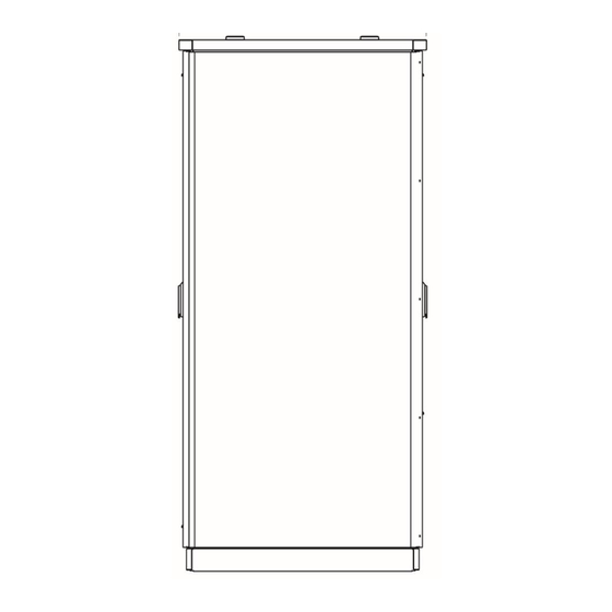
Page 11: Cabinet Orientation
3 June 2022 Cabinet Orientation The front door of the PKM150 RU provides access to the (up to) four DC Isolators that allow power to be supplied to the connected charging stations. The rear door of the cabinet provides access to the electrical wiring, fans, and other connections for the purposes of installation and servicing. -
Page 12: Site Preparation
PKM150RU Installation Manual TRI156.INS.2022 version 2 3 June 2022 Site Preparation Foundation – precast preparation 4.3.1 Ensure that all cables are pulled and labelled as per the cabling plan, see TRI155.INS.1968_PKM150 Piping and Cabling for more information on cable requirements. Ensure TRI156-18833 Foundation Plate or TRI156-20104 Paired RU Foundation Plate is set on the concrete slab to assist leveling the base and locating masonry anchors. -
Page 13: Installation Kit Contents
DCP EPO link harness 20665 Low profile black 3G/4G LTE omni-directional antennae 14810 M12 Nyloc Flange Nut 15425 4.4.2 Unbox the PKM150 RU Remove the top and side box panels and remove the cable entry contents. TEM114v3_Manual Page 13 of 29... -
Page 14: Cable Entry Module Installation
PKM150RU Installation Manual TRI156.INS.2022 version 2 3 June 2022 Cable Entry Module Installation Frame Install the Cable Entry Frame assembly over the foundation plate threaded studs and conduit. Apply anti-seize, and fix down using 6 x M8 nuts, tightening the nuts to 10Nm. DC Output Gland Plate Fasten the DC output gland plate to the rear of the cable entry frame and fasten with 4x M6 bolts. -
Page 15: Ac Input Connections
PKM150RU Installation Manual TRI156.INS.2022 version 2 3 June 2022 AC Input Connections Remove the six terminal blocks from the AC DIN rail assembly. Remove the 3x M6x50 Pan head screws and nuts that connect the front section of the cable clamps. Remove the front section of the cable clamps (leave the rear piece in place to protect the cable insulation). - Page 16 PKM150RU Installation Manual TRI156.INS.2022 version 2 3 June 2022 Bolt the DC gland plate to the AC gland plate as shown. Thread all the AC input cables in the correct position as per the cable layout. Measure and cut the AC cables 135mm from the AC gland plate surface. Strip back 45-47mm from the end.
- Page 17 PKM150RU Installation Manual TRI156.INS.2022 version 2 3 June 2022 Secure the clamps in the following order: Fit the two sides of the clamp together with the AC cables between. Loosely tighten the pan head bolt to secure the clamp. Loosely tighten the M6 Nyloc flange nuts in order. Fit cable connection block over the cable and connect to the DIN rail.
- Page 18 3 June 2022 Use cable ties to bundle together the long power cables. If the PKM150 RU is being installed at a later stage Tritium has a lockable RU Foundation cover available to protect the site. Contact your Tritium representative for further information.
-
Page 19: Rectifier Unit Installation
(may vary). Lift cabinet over the cable entry framework and lower onto the foundation Bolt the PKM150 RU to the foundation using 4 x M12 Flange Nyloc Nuts, applying anti- seize to all fasteners. Remove all lifting equipment. -
Page 20: Cable Termination
PKM150RU Installation Manual TRI156.INS.2022 version 2 3 June 2022 Cable Termination 6.2.1 AC Protective Earth Connect the protective earth cable on the AC filter tray to the main earth bar on the rear of the cable entry module using the supplied 120mm² earth cable. 6.2.2 High Power 3-Phase AC Input Connect the AC Input cables to the Terminals as shown below. -
Page 21: High Power Dc Output
6.2.3 High Power DC Output Remove all DC HP covers situated in the centre of the PKM150 RU. Connect the High-Power DC Output cables to the DC Ports using M10 nuts and washers, tightening to 30Nm and applying copper jointing compound. Orientate cabling as shown. -
Page 22: Termination - Emergency Power-Off Wiring
Termination – Emergency Power-Off Wiring 6.2.4 The PKM150 RU has several auxiliary control wires that must be terminated within the cabinet. These wires can be split into two groups – wiring between the upstream supply switchboard and the PKM150 RU, and wiring between the PKM150 RU and any installed PKM150 CS units. -
Page 23: Upstream Emergency Power-Off Terminations
This is to ensure that under emergency fault conditions (such as opening of a door while the unit is powered, or triggering of the unit’s tilt switch), the PKM150 RU will be able to remove power safely and quickly from the cabinet. -
Page 24: 3-Wire Uv Trip
PKM150RU Installation Manual TRI156.INS.2022 version 2 3 June 2022 6.2.5.1.1. 3-Wire UV Trip 3-wire UV wiring configuration for the upstream trip of the PKM150 RU has the following benefits: • Safe PKM150 RU power state under emergency fault conditions. •... -
Page 25: Main Switch Shunt-Trip
6.2.5.2. Main Switch Shunt-Trip The shunt trip configuration has the upstream trip start-up delay timer pre-built into the PKM150 RU. It is also connected by default to the door switch sensing circuit. It has the following benefits: • Safe PKM150 RU power state under emergency fault conditions. - Page 26 PKM150RU Installation Manual TRI156.INS.2022 version 2 3 June 2022 DC Isolator Shunt Trip Note: Refer to the PKM150 CS Installation Manual to ensure the correct terminals on the PKM150 CS are wired to the PKM150 RU. TEM114v3_Manual Page 26 of 29...
-
Page 27: Termination - Networking
IMPORTANT Ensure that all conductors of the network cables, including the shield, are connected completely between the PKM150 CS and the PKM150 RU network switch. Failure to do so may lead to network dropouts and intermittent communications. External Network – Hardwired (optional) 6.2.6.2. -
Page 28: Networking - Sim Card Installation
PKM150RU Installation Manual TRI156.INS.2022 version 2 3 June 2022 Networking – SIM Card Installation To Install the SIM card (if not already installed) follow the below steps: Ensure the switch on/off switch is in the off position and disconnect the two antennae cables from the SMA connections to the left of the switch. -
Page 29: Review Of Document
PKM150RU Installation Manual TRI156.INS.2022 version 2 3 June 2022 Review of document This document is reviewed and updated regularly in accordance with PRO.019 Documentation Continuous Review Process. Revision record Date TC # Change Author 22 March 2022 3258 Initial version S.
Need help?
Do you have a question about the PKM150 and is the answer not in the manual?
Questions and answers