Table of Contents

Related Manuals for intensity KJR-90A


Summary of Contents for intensity KJR-90A
- Page 1 WIRE CONTROLLER KJR-90A INSTALLATION & OWNER´S MANUAL Thank you very much for purchasing our product. Before using your unit, please read this manual carefully and keep it for future reference. intensity.mx MAN-O-KJR90A-0416...
- Page 3 This manual gives detailed description of the precautions that should be brought to your attention during operation. ease read this manual carefully before using the unit. reading it.
-
Page 4: Table Of Contents
CONTENTS 1. Safety precautions.............1 2. Installation accessory ..........3 3. Installation method.............4 4. Wiring diagram for wiring wire controller with air conditioner..............7 5. Specification...............8 6. General functionler ............8 7. Name and operation of the button on the wire controller ..............9 8. Indicators and functions..........14 9. -
Page 5: Safety Precautions
1. Safety precautions Read the safety precautions carefully before installing the unit. Stated below are important safety issues that must be obeyed. Means improper handling may lead to personal WARNING death or severe injury. Means improper handling may lead to personal CAUTION injury or property loss. - Page 6 1. Safety precaution Do not uninstall the unit randomly. Random uninstalling may lead to abnormal operation, heating or fire of the air condition. NOTE Do not install the unit in a place vulnerable to leakage of flammable gases. Once flammable gases are leaked and left around the wire controller, fire may occure.
-
Page 7: Installation Accessory
2. Installation accessory Select the installation location Don’t install at the place where contents with heavy oil, vapor or sulfureted gas, otherwise, this product would be deformed that would lead to system malfunction. Preparation before installation 1. Please confirm that all the following parts you have been supply. Qty. -
Page 8: Installation Method
3. Installation method Simplified schematic of wire controller Transmitting tube wire controller Employ shielded 5-core wire for connection the in here, the length should be set base Indoor unit display panel on field installation(<15m). Indoor unit Fig 3-1 Installation diagram Connective wires for the display panel (accessory) The shielded 5-core wire Display panel... - Page 9 3. Installation method If there is no terminal, the 5-core wire should be connected directly. The shielded 5-core wire pre-embedded into wall. Fig 3-3 Fig 3-4...
- Page 10 3. Installation method Fig 3-5 1. Connect the male joint of 5-core wires group of the display panel with the female 5-core terminal of display panel. (See Fig.3-2) 2. Please connect the other side of display panel with the wall pre-bedded 5-core cable reliability.
-
Page 11: Wiring Diagram For Wiring Wire Controller With Air Conditioner
4. Wiring diagram for wiring wire controller with air conditioner Indoor unit The rear side of electric cabinet wire controller Insert of the electric control A B C D E Electric control of indoor unit 10-cored Shielded 5-core cable (See Installation connective wires preparation sheet 1 for the specification.) Connective wires... -
Page 12: Specification
5. Specification Input voltage DC 5V Ambient temperature -5~43ºC Ambient humidity RH40%~RH90% 6. General function Main functions of this wire controller as follows: Connect with indoor unit via the five ports of A, B, C, D, E. Set operation mode via buttons control. Provided with LCD display function. -
Page 13: Name And Operation Of The Button On The Wire Controller
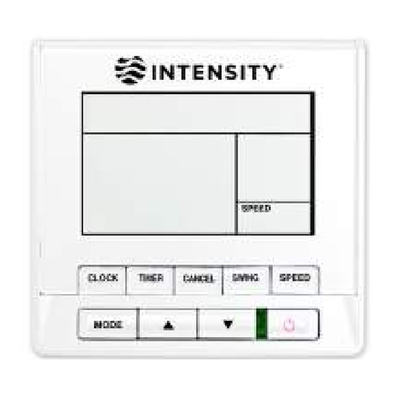
7. Name and operation of the button on the wire controller CLOCK TIMER CANCEL SWING SPEED MODE MODE Select Button Adjust Button TIMER Button ON/OFF Button Time Button SWING Button Adjust Button CANCEL Button FAN SPEED Button... - Page 14 7. Name and operation of the button on the wire controller signal received SPEED CLOCK TIMER CANCEL SWING NO Use Adjust Button TIMER Button ON/OFF Button Time Button SWING Button Adjust Button CANCEL Button FAN SPEED Button...
- Page 15 7. Name and operation of the button on the wire controller CLOCK TIMER CANCEL MODE TEMP TEMP SWING MODE Select Button Adjust Button TIMER Button ON/OFF Button Time Button SWING Button Adjust Button CANCEL Button FAN SPEED Button Infrared remote receiver...
- Page 16 7. Name and operation of the button on the wire controller ① MODE Select Button: Each time you push the button, a mode is selected in a sequence that goes from AUTO,COOL,DRY,HEAT and FAN as the following figure indicates: AUTO COOL HEAT NOTE...
- Page 17 7. Name and operation of the button on the wire controller ⑤ Time Button: Normally, LCD displays the current time of the setting clock (however, LCD would display 12:00 when the first time power to the wire controller or reset the wire controller).
-
Page 18: Indicators And Functions
8. Indicators and functions AUTO COOL HEAT TIME ON TEMP SET TIME OFF SPEED Operation mode indication Temperature display zone Time ON indication Time indication Time OFF indication Fan speed indication... - Page 19 8. Indicators and functions ① Operation mode indication: Press MODE to display current running mode. AUTO, COOL, DRY, HEAT and FAN can be selected. (HEAT function is invalid for cool only type unit.) ② Temperature display zone: Display the set temperature. Adjust temperature via .
-
Page 20: Operation Instructions
9. Operation instructions 9.1 AUTO operation Switch on the power and running indicator light on indoor unit flashes. 1. Press MODE to select AUTO. 2. Adjust temp via . Generally the range is 17 ºC ~30ºC. 3. Press ON/OFF and running indicator light on indoor unit is lightened. Air conditioner will work on AUTO mode and fan speed is AUTO which is non adjustable. - Page 21 9. Operation instructions 3. Press FAN SPEED to select AUTO, LOW, MED or HIGH. 4. Press ON/OFF and running indicator light on indoor unit is lightened. Air conditioner will work on the set mode. Stop operation via ON/OFF. NOTE The FAN mode cannot be used to control the temperature. While in this mode, only steps 1 3 and 4 may be performed.
- Page 22 9. Operation instructions 9.4 Timing set TIMER button is for set TIME ON /TIME OFF these two types of timing. Timing ON time and CLOCK are display at the same displayed zone. When the Timing ON has been set, the CLOCK displayed zone would show the Timing ON information.
- Page 23 9. Operation instructions 9.4-2 Set Timing ON and OFF In case originally provide with timing set in the system, please press the CANCEL button to cancel the current settings. 1. Press the TIMER button, the LCD in the wire controller will show “TIME ON”, at the same time the time zone will display the last setting time, which flash at the frequency of 1Hz, the wire control enters to Timing ON status.
- Page 24 The design and specifications are subject to change without prior notice for product improvement. Consult with the sales agency or manufacturer for details.
Need help?
Do you have a question about the KJR-90A and is the answer not in the manual?
Questions and answers