
Related Manuals for Sfera Labs Strato X2 Series


Summary of Contents for Sfera Labs Strato X2 Series
- Page 1 Industrial Digital I/O X2-Series Expansion Board March 2024 Revision 001 X2BI10XD7 Industrial Digital I/O X2-Series Expansion Board ...
-
Page 2: Table Of Contents
Safety information Qualified personnel Hazard levels Safety instructions General safety instructions Introduction Features Device identification Hardware setup Connections Power supply Digital input/output section Power and status LEDs Using the Digital I/O expansion board IN1-IN7 digital inputs OUT1-OUT7 digital outputs OUT1-OUT7 connection and protection Overvoltage protection Thermal protection Advanced usage... - Page 3 Please download and read the Sfera Labs Terms and Conditions document available at: http://www.sferalabs.cc Strato and Sfera Labs are trademarks of Sfera Labs S.r.l. Other brands and names may be claimed as the property of others. Copyright © 2024 Sfera Labs S.r.l. All rights reserved.
-
Page 4: Safety Information
Safety information Carefully and fully read this user guide before installation and retain it for future reference. Qualified personnel The product described in this manual must be operated only by personnel qualified for the specific task and installation environment, in accordance with all relevant documentation and safety instructions. -
Page 5: Safety Instructions
Safety instructions General safety instructions Protect the unit against moisture, dirt and any kind of damage during transport, storage and operation. Do not operate the unit outside the specified technical data. Never open the housing. If not otherwise specified, install in closed housing (e.g. distribution cabinet). -
Page 6: Introduction
Introduction The X2-Series X2BI10XD7 Industrial Digital I/O expansion board provides 7 current- sinking 24 V IEC 61131-2 compliant industrial digital inputs with diagnostics and 7 640 mA, 24 V outputs that can be configured as high-side switches or push-pull drivers. The output lines have a dedicated on-board power supply input, independent of the Strato Pi Max power supply. -
Page 7: Features
Features ✓ 12÷28 Vdc dedicated I/O power supply ✓ 7 current-sinking 24 V IEC 61131-2 compliant industrial digital inputs with diagnostics, based on MAX22190 ✓ 7 640 mA, 24 V outputs that can be configured as high-side switches or push-pull drivers for high-speed switching, based on MAX14912/MAX14913 ✓... -
Page 8: Device Identification
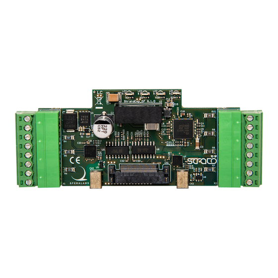
Device identification The circuit board is identified by the "StratoExp_D7 R.1.0" markings on the lower left corner of the circuit board (front view). One or more alphanumeric characters may be printed after the version number. CIRCUIT BOARD IDENTIFICATION MARKINGS X2BI10XD7 User Guide... -
Page 9: Hardware Setup
Hardware setup Connections TERMINAL BLOCKS CONNECTIONS In order to install or remove the expansion board, the plastic DIN rail enclosure must be removed NOTICE Before opening the Strato Pi Max enclosure, disconnect all power sources and any connection to external devices, including USB and Ethernet cables. Follow the Strato Pi Max User Guide installation instructions. -
Page 10: Digital Input/Output Section
Digital input/output section ✓ DC: nominal voltage between 12 V and 28 V (min=10.5 V, max=36 V) Respect the correct polarity: ground must be connected to I/O V- and positive voltage level to I/O V+. I/O V+ is not required for the inputs. The I/O V- connection is always required. Power and status LEDs This expansion board has four LEDs, visible through the front panel: A. -
Page 11: Using The Digital I/O Expansion Board
These protection mechanisms are implemented in the standard Strato Pi Max firmware provided by Sfera Labs. If the user uses custom firmware the protection logic described below shall be implemented. Some use cases may require the implementation of different or additional protection logic, or be subject to other electrical and operational limitations. -
Page 12: Overvoltage Protection
Overvoltage protection When an output line of the MAX14912/MAX14913 driver is configured as high-side and set to OFF, if a voltage is applied to that line that is higher than 0.3V + I/O V+, a considerable amount of current will flow from the output to the MAX14912/MAX14913 VDD, and to the I/ O V+ terminal, if it is connected. -
Page 13: Advanced Usage
Advanced usage RP2040 I²C bus addresses The following table lists all components connected to the RP2040 I²C bus, and their R/W addresses. SLOT ADDR WRITE READ MCP23008 0x24 [100100] 0x48 0x49 0x25 [100101] 0x4A 0x4B 0x26 [100110] 0x4C 0x4D 0x27 [100111] 0x4E 0x4F X2BI10XD7 User Guide... -
Page 14: I²C Configuration And Control Registers Map
I²C Configuration and control registers map Installing one or more Industrial Digital I/O Expansion Board on Strato Pi Max adds the following registers to its I²C map. The registers’ addresses below correspond to the board installed in slot 1. Add 10 for each upper slots, i.e. - Page 15 0 = disabled (default) 1 = Outputs 4-5 and 6-7 joined. The joined 4-5 outputs configuration will be DO4 CFG. The joined 6-7 outputs configuration will be DO6 CFG. DO4 CFG and DO6 CFG shall have a value of 0, 1, or 2 only (a value of 3 is switched to Register 103 (R) Bit 0, …, 6 DIn: Digital input n state...
- Page 16 Register 107 (R) Bit 0, …, 6 OTn: Digital output n thermal shutdown 0 = not active 1 = active X2BI10XD7 User Guide...
-
Page 17: Block Diagram
Block diagram X2BI10XD7 User Guide... -
Page 18: Technical Specifications
Technical specifications Note: all values typical, at +25 °C and under normal operating conditions. POWER SUPPLY I/O supply operating voltage 12…28 V⎓ nom. (10.5…36 V⎓ ) I/O input current Max 20 mA + ∑ OUT1-OUT7 IN1-IN7: DIGITAL INPUTS Input voltage range +0…+36 V Input current 2.4 mA... - Page 19 width: 84.3 mm Dimensions height: 41.1 mm depth: 14.5 mm Weight 35 g (including terminal blocks and screws) X2BI10XD7 User Guide...
-
Page 20: Dimensions
Dimensions DIMENSIONS (mm) X2BI10XD7 User Guide... -
Page 21: Disposal
Disposal Waste Electrical & Electronic Equipment (Applicable in the European Union and other European countries with separate collection systems). This marking on the product, accessories or literature indicates that the product should not be disposed of with other household waste at the end of their working life. To prevent possible harm to the environment or human health from uncontrolled waste disposal, separate these items from other types of waste and recycle them responsibly to promote the sustainable reuse of material resources. -
Page 22: Conformity Information
Conformity Information This device complies with the following applicable European Community harmonised standards: ✓ 2014/30/EU - Electromagnetic Compatibility Directive (EMC) ✓ 2011/65/EU and 2015/863/EU - Restriction of the use of certain hazardous substances in electrical and electronic equipment (RoHS 3) The following harmonised standards have been used to demonstrate conformity to these directives: ✓... -
Page 23: Canada
CANADA This Class B digital apparatus complies with Canadian ICES-003. Cet appareil numérique de la classe B est conforme à la norme NMB-003 du Canada. RCM AUSTRALIA / NEW ZEALAND This product meets the requirements of the standard EN 61000-6-3: 2021 - Emission for residential, commercial and light-industrial environments.
Need help?
Do you have a question about the Strato X2 Series and is the answer not in the manual?
Questions and answers