Table of Contents
Advertisement
Quick Links
AE4-1428 R1
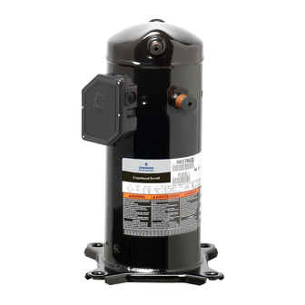
6 to 10 Ton ZPS*KC Copeland Scroll™ Two-Stage Compressors
Safety
Safety Instructions .................................................... 2
Safety Icon Explanation ............................................ 2
Shock, Fire, or Injury to Persons ............................... 3
Safety Statements .................................................... 3
How It Works ........................................................... 4
Capacity Control ...................................................... 4
Nomenclature .......................................................... 4
Operating Envelope ................................................. 4
High Pressure Control .............................................. 5
Low Pressure Control ............................................... 5
Discharge Temperature Protection........................5
Crankcase Heat ....................................................... 5
Defrost Cycle ........................................................... 5
Unloader Solenoid Wiring ......................................... 5
Standard Wiring with 24 Volts................................... 5
Part-Load Starting .................................................... 6
Wiring with CoreSense™ Diagnostics.....................6
© 2017 Emerson Climate Technologies, Inc.
TABLE OF CONTENTS
Application Tests......................................................6
Hipot (AC High Potential) Testing ............................. 6
Unloader Test Procedure with 24 Volts ..................... 6
Unloader Test Procedure with CoreSense™ ............. 7
Figures
ZPS*KC Modulation Hardware .................................. 4
Operating Envelope .................................................. 8
24 Volt Modulation Control Wiring ............................. 8
Modulation Control Wiring with CoreSense™ ............ 9
Crankcase Heater Location....................................... 9
Tables
Compressor Refrigerant Charge Limits ..................... 10
Solenoid Resistance Value ....................................... 10
Compressor Accessories .......................................... 11
1
October 2018
Advertisement
Table of Contents

Summary of Contents for Emerson Copeland Scroll ZPS KC Series
-
Page 1: Table Of Contents
Compressor Refrigerant Charge Limits ..... 10 Defrost Cycle ............5 Solenoid Resistance Value ........10 Unloader Solenoid Wiring ......... 5 Compressor Accessories .......... 11 Standard Wiring with 24 Volts........5 Part-Load Starting ............ 6 Wiring with CoreSense™ Diagnostics…………………6 © 2017 Emerson Climate Technologies, Inc. -
Page 2: Safety Instructions
NOTICE NOTICE is used to address practices not related to personal injury. CAUTION, without the safety alert symbol, is used to address practices not related CAUTION to personal injury. © 2017 Emerson Climate Technologies, Inc. -
Page 3: Instructions Pertaining To Risk Of Electrical Shock, Fire, Or Injury To Persons
Only qualified and authorized HVAC or refrigeration personnel are permitted to install commission and maintain this equipment. • Electrical connections must be made by qualified electrical personnel. • All valid standards and codes for installing, servicing, and maintaining electrical and refrigeration equipment must be observed. © 2017 Emerson Climate Technologies, Inc. -
Page 4: Introduction
Application Engineering for more information. The within the scroll that are compressing gas. Modulation envelope represents acceptable operating conditions is achieved by venting a portion of the gas in the first © 2017 Emerson Climate Technologies, Inc. -
Page 5: High Pressure Control
High Pressure Control Available crankcase heaters are listed in AE4-1365 or A high-pressure cut-out is recommended for the Emerson.com/OPI. Refer to Figure 5 for proper highest level of system reliability. If a high-pressure installation of the crankcase heater. cut-out control is used the maximum setting should not exceed 650 psig (45 bar). -
Page 6: Part-Load Starting
(18 to 28 VAC). The measured DC voltage application. Consult with your Emerson Climate at the connectors in the plug should be around 15 Technologies Application Engineer if interpretation of to 27 VDC. -
Page 7: Unloader Test Procedure With Coresense
Fault Code 1 or 9 is active. 3. If the correct DC voltage is at the control circuit molded plug measure the unloader coil resistance. The solenoid coil should have continuity and not © 2017 Emerson Climate Technologies, Inc. -
Page 8: Operating Envelope
AE4-1428 R1 Figure 2 Full Load Operating Envelope Figure 3 Example of 24 Volt Modulation Control Wiring © 2017 Emerson Climate Technologies, Inc. -
Page 9: Modulation Control Wiring With Coresense
Figure 5 Crankcase Heater Location Connect the heater so that the connection point straddles the compressor seam weld. WARNING Verify the correct crankcase heater voltage for the application and ensure heater is properly grounded © 2017 Emerson Climate Technologies, Inc. -
Page 10: Compressor Refrigerant Charge Limits
12.0 ZPS104 - 122KC 13.0 *Approximate Shell Diameter (e.g. 70 = 7.3 Inches) **Charge Allowance For System Table 2 - Solenoid Resistance Values Compressor Compressor Solenoid Resistance Family Models 1640 Ω ZPS*KC All Models © 2017 Emerson Climate Technologies, Inc. -
Page 11: Compressor Accessories
Emerson Climate Technologies, Inc. and/or its affiliates (collectively "Emerson"), as applicable, reserve the right to modify the design or specifications of such products at any time without notice. Emerson does not assume responsibility for the selection, use or maintenance of any product.


Need help?
Do you have a question about the Copeland Scroll ZPS KC Series and is the answer not in the manual?
Questions and answers