
Related Manuals for GigaDevice Semiconductor Arm Cortex M23


Summary of Contents for GigaDevice Semiconductor Arm Cortex M23
- Page 1 GigaDevice Semiconductor Inc. GD32L233R-EVAL ® ® Cortex -M23 32-bit MCU User Guide Revision 1.1 (Nov. 2021)
-
Page 2: Table Of Contents
User Guide GD32L233R-EVAL Table of Contents Table of Contents......................... 1 List of Figures ........................4 List of Tables ........................5 1. Summary......................... 6 2. Function Pin Assign...................... 7 3. Getting started ....................... 9 4. Hardware layout overview ..................10 Power supply......................10 4.1. - Page 3 User Guide GD32L233R-EVAL 5.5.2. DEMO running result ....................19 USART_DMA ......................19 5.6. 5.6.1. DEMO purpose ......................19 5.6.2. DEMO running result ....................19 LPUSART_Deepsleep_Wakeup ................20 5.7. 5.7.1. DEMO purpose ......................20 5.7.2. DEMO running result ....................20 ADC_Temperature_Vrefint ..................21 5.8. 5.8.1. DEMO purpose ......................21 5.8.2.
- Page 4 User Guide GD32L233R-EVAL 5.20.1. DEMO purpose ......................29 5.20.2. DEMO running result ....................29 5.21. LPTIMER_Deepsleep_Pwmout ................30 5.21.1. DEMO purpose ......................30 5.21.2. DEMO running result ....................30 SLCD_Glass ......................30 5.22. 5.22.1. DEMO purpose ......................30 5.22.2. DEMO running result ....................30 USBD_Keyboard ....................30 5.23.
-
Page 5: List Of Figures
User Guide GD32L233R-EVAL List of Figures Figure 4-1. Schematic diagram of power supply .................10 Figure 4-2. Schematic diagram of boot option ................10 Figure 4-3. Schematic diagram of LED function................10 Figure 4-4. Schematic diagram of Key function ................11 Figure 4-5. Schematic diagram of ADC ..................11 Figure 4-6. -
Page 6: List Of Tables
User Guide GD32L233R-EVAL List of Tables Table 2-1. Function pin assignment .................... 7 Table 6-1. Revision history ......................33 5/34... -
Page 7: Summary
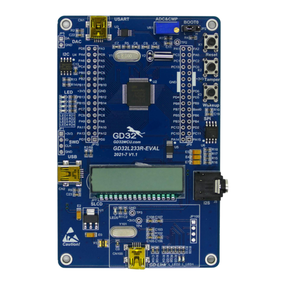
User Guide GD32L233R-EVAL Summary GD32L233R-EVAL uses GD32L233RCT6 as the main controller. It uses GD-Link Mini USB interface to supply 5V power. Reset, Boot, Button key, LED, I2S, I2C-EEPROM, SLCD, QSPI- Flash, USB and USART to USB interface are also included. For more details, please refer to GD32L233R-EVAL_Rev1.1 schematic. -
Page 8: Function Pin Assign
User Guide GD32L233R-EVAL Function Pin Assign Table 2-1. Function pin assignment Function Description LED1 LED2 LED3 PC11 LED4 RESET Reset P A0 K3(Wakeup) PC13 K2(Tamper) P A1 ADC_IN1 P A4 DAC_OUT P A2 USART1_TX USART P A3 USART1_RX PB10 I2C1_SCL PB11 I2C1_SDA PC12... - Page 9 User Guide GD32L233R-EVAL Function Description SEG22 SEG23 P A1 CMP0_IP P A11 USB_DM P A12 USB_DP 8/34...
-
Page 10: Getting Started
User Guide GD32L233R-EVAL Getting started The EVAL board uses GD-Link Mini USB connecter to get power DC +5V, which is the hardware system normal work voltage. A GD-Link on board is necessary in order to download and debug programs. Select the correct boot mode and then power on, the LEDPWR will turn on, which indicates the power supply is OK. -
Page 11: Hardware Layout Overview
User Guide GD32L233R-EVAL Hardware layout overview 4.1. Power supply Figure 4-1. Schematic diagram of power supply POWER +U5V +5V0 SMD1210P050TF +3V3 TP +3V3 +5V0 AMS1117-3.3 LED5 16V/10uF,AVX 16V/10uF,AVX LED0603 Vout 470Ω 50V/0.1uF 4.2. Boot option Figure 4-2. Schematic diagram of boot option 4.3. -
Page 12: Key
User Guide GD32L233R-EVAL 4.4. Figure 4-4. Schematic diagram of Key function 4.5. Figure 4-5. Schematic diagram of ADC 4.6. Figure 4-6. Schematic diagram of DAC 4.7. Figure 4-7. Schematic diagram of CMP 11/34... -
Page 13: Usart
User Guide GD32L233R-EVAL 4.8. USART Figure 4-8. Schematic diagram of USART +3V3 VBUS 50V/0.01uF USART1_TX USART1_RX RTS# +3V3 CTS# TNOW CH340E 50V/0.1uF Shield Mini_USB 1MΩ 50V/4700pF 4.9. Figure 4-9. Schematic diagram of I2C 4.10. Figure 4-10. Schematic diagram of I2S 12/34... -
Page 14: Spi
User Guide GD32L233R-EVAL 4.11. Figure 4-11. Schematic diagram of SPI 4.12. SLCD Figure 4-12. Schematic diagram of SLCD SLCD COM0 100Ω COM1 100Ω PA10 COM2 100Ω COM3 100Ω SEG6 SEG16 PB12 SEG12 PB13 SEG13 PB14 SEG14 PB15 SEG15 SEG18 SEG19 SEG20 SEG21 SEG22... -
Page 15: Extension
User Guide GD32L233R-EVAL 4.14. Extension Figure 4-14. Schematic diagram of Extension Extention JP10 PA15 PA14 PC11 PC10 PA12 PA13 PC12 PA10 PA11 BOOT0 PB14 PB15 PB12 PB13 +3V3 PB10 PB11 +3V3 PC13 HEADER 16X2 HEADER 16X2 4.15. GD-Link Figure 4-15. Schematic diagram of GD-Link 14/34... - Page 16 User Guide GD32L233R-EVAL MCU SWD PA0-WKUP +3V3 JP100 PB2/BOOT1 L_SWDIO PB3/JTDO L_SWDCK L_TMS/IO PB4/JNTRST L_TCK/CLK L_TDO/SWO 4× 1P2.54 L_TDI L_USB_Ctr L_TReset L_LED1 LED0603 Reset PA10 PB10 L_USB_DM PA11 PB11 +3V3 L_USB_DP L_LED1 R109 470Ω PA12 PB12 L_SWDIO L_LED2 R110 470Ω PA13/JTMS/SWDIO PB13 L_SWDCK...
-
Page 17: Mcu
User Guide GD32L233R-EVAL 4.16. Figure 4-16. Schematic diagram of MCU +3V3 PA13 SWDAT PA14 SWCLK PB2/BOOT1 HEADER 4 HC-49S-8MHz OSC_IN PA10 PB10 PA10 PB10 PA11 PB11 PA11 PB11 50V/20pF PA12 PB12 PA12 PB12 1MΩ PA13 PB13 PA13/SWDIO PB13 OSC_OUT PA14 PB14 PA14/SWCLK PB14... -
Page 18: Routine Use Guide
User Guide GD32L233R-EVAL Routine use guide 5.1. GPIO_Running_LED DEMO purpose 5.1.1. This demo includes the following functions of GD32 MCU: Learn to use GPIO control the LED Learn to use SysTick to generate 1ms delay GD32L233R-EVAL board has two user keys and four LEDs. The keys are Tamper key, and Wakeup key. -
Page 19: Exti_Key_Interrupt_Mode
User Guide GD32L233R-EVAL 5.3. EXTI_Key_Interrupt_mode DEMO purpose 5.3.1. This demo includes the following functions of GD32 MCU: Learn to use GPIO control the LED and the KEY Learn to use EXTI to generate external interrupt GD32L233R-EVAL board has two user keys and four LEDs. The keys are Tamper key and Wakeup key. -
Page 20: Usart_Hyperterminal_Interrupt
User Guide GD32L233R-EVAL 5.5. USART_HyperTerminal_Interrupt DEMO purpose 5.5.1. This demo includes the following functions of GD32 MCU: Learn to use the USART transmit and receive interrupts to communicate with the HyperTerminal. DEMO running result 5.5.2. Download the program <05_USART_HyperTerminal_Interrupt> to the EVAL board and connect serial cable to USART. -
Page 21: Lpusart_Deepsleep_Wakeup
User Guide GD32L233R-EVAL output the received data to the hyper terminal. The output information via the HyperTerminal is as following: 5.7. LPUSART_Deepsleep_Wakeup DEMO purpose 5.7.1. This demo includes the following functions of GD32 MCU: Learn to use the LPUART wakeup the MCU from DEEPSLEEP mode. DEMO running result 5.7.2. -
Page 22: Adc_Temperature_Vrefint
User Guide GD32L233R-EVAL 5.8. ADC_Temperature_Vrefint DEMO purpose 5.8.1. This demo includes the following functions of GD32 MCU: Learn to use the ADC to convert analog signal to digital data Learn to get the value of inner channel 16 (temperature sensor channel) and channel 17 (Vrefint channel) DEMO running result 5.8.2. -
Page 23: Comparator_Obtain_Brightness
User Guide GD32L233R-EVAL value is 1.65V. 5.10. Comparator_obtain_brightness DEMO purpose 5.10.1. This Demo includes the following functions of GD32 MCU: Learn to use comparator output compare result There are two comparators on EVAL board and each comparator has two inputs. In this demo, one input is connected to VR1, and the other one is the reference voltage (1.2V). -
Page 24: Qspi_Flash
User Guide GD32L233R-EVAL 5.12. QSPI_FLASH DEMO purpose 5.12.1. This demo includes the following functions of GD32 MCU: Learn to use the Quad-SPI mode of SPI unit to read and write NOR Flash with the SPI interface DEMO running result 5.12.2. -
Page 25: I2S_Audio_Player
User Guide GD32L233R-EVAL are written to and read from flash. Compare the data that were written to the flash and the data that were read from the flash. If they are the same, the serial port will output “SPI- GD25Q16 Test Passed!”, otherwise, the serial port will output “Err: Data Read and Write aren' t Matching.”. -
Page 26: Demo Running Result
User Guide GD32L233R-EVAL DEMO running result 5.13.2. Download the program<13_I2S_Audio_Player>to the EVAL board, insert the headphone into the audio port, and then listen to the audio file. 5.14. TRNG_Get_Random DEMO purpose 5.14.1. This demo includes the following functions of GD32 MCU: ... -
Page 27: Demo Running Result
User Guide GD32L233R-EVAL Learn to communicate with PC by USART DEMO running result 5.15.2. Download the program <15_CAU> to the EVAL board and run. When the program is running, the serial terminal tool will display the information, as shown in the following figure. Plaintext data value, the encryption algorithm, and the mode can be selected are shown. -
Page 28: Rcu_Clock_Out
User Guide GD32L233R-EVAL below. 5.16. RCU_Clock_Out DEMO purpose 5.16.1. This demo includes the following functions of GD32 MCU: Learn to use GPIO control the LED Learn to use the clock output function of RCU Learn to communicate with PC by USART DEMO running result 5.16.2. -
Page 29: Demo Running Result
User Guide GD32L233R-EVAL calibration function Learn to use clock trim controller (CTC) to trim internal 48MHz RC oscillator (IRC48M) clock The CTC unit trim the frequency of the IRC48M based on an external accurate reference signal source. It can automatically adjust the trim value to provide a precise IRC48M clock. DEMO running result 5.17.2. -
Page 30: Timer_Breath_Led
User Guide GD32L233R-EVAL 5.20. TIMER_Breath_LED DEMO purpose 5.20.1. This Demo includes the following functions of GD32 MCU: Learn to use TIMER output PWM wave Learn to update TIMER channel value DEMO running result 5.20.2. Download the program <20_TIMER_Breath_LED> to the GD32L233R-EVAL board and run. When the program is running, you can see LED1 lighting from dark to bright gradually and 29/34... -
Page 31: Lptimer_Deepsleep_Pwmout
User Guide GD32L233R-EVAL then gradually darken, ad infinitum, just like breathing as rhythm. LPTIMER_Deepsleep_Pwmout 5.21. DEMO purpose 5.21.1. This Demo includes the following functions of GD32 MCU: Learn to use LPTIMER output PWM wave Learn to use the LPTIMER interrupts to wake up the PMU from sleep mode DEMO running result 5.21.2. -
Page 32: Demo Running Result
User Guide GD32L233R-EVAL Host HID driver, as shown below. The USB Keyboard uses Tamper key and Wakeup key to output two characters (‘a’, ‘b’). In addition, the demo also supports remote wakeup which is the ability of a USB device to bring a suspended bus back to the active condition, and the ‘b’ key is used as the remote wakeup source. -
Page 33: Demo Running Result
User Guide GD32L233R-EVAL DEMO Running Result 5.24.2. Download the program <24_USBD_CDC_ACM> to the EVAL board and run. When user input message through computer keyboard, the HyperTerminal will receive and shown the message. For example, when you input “GigaDevice MCU”, the HyperTerminal will get and show it as below. -
Page 34: Revision History
User Guide GD32L233R-EVAL Revision history Table 6-1. Revision history Revision No. Description Date Initial Release Aug.15, 2021 Update the format Nov.15, 2021 33/34... - Page 35 Important Notice This document is the property of GigaDevice Semiconductor Inc. and its subsidiaries (the "Company"). This document, including any product of the Company described in this document (the “Product”), is owned by the Company under the intellectual property laws and treaties of the People’s Republic of China and other jurisdictions worldwide.
Need help?
Do you have a question about the Arm Cortex M23 and is the answer not in the manual?
Questions and answers