Advertisement
Quick Links
Overview
The HPX-U100-2BTN HydraPort 2-Button Keypad Module (FG554-02) with LEDs is a
HydraPort module that enable users to switch to a specific input in Solecis digital
switcher applications, or perform an action when configured for I/O operation with AMX
master controllers, and DVX presentation switchers. The buttons can be illuminated
when it is active, making it easy to determine which device's content is being shown on
the display at any given time. Multiple modules can be stacked to accommodate a large
number of devices. An optional Accessory kit (FG554-08) provides colored button
inserts and similarly colored tags that fit onto the end of a cable where it plugs into the
device, making it easy to identify which button selects an input.
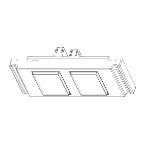
The HPX-U100-2BTN HydraPort Two-Button Module (FIG. 1) is designed to be used in
conjunction with the HPX-600/900/1200/1800 or HydraPort Touch (7"/10")
Connection Ports and takes up 1 HydraPort unit.
FIG. 1
HPX-U100-2BTN TWO-BUTTON MODULE
Product Specif ications
HPX-U100-2BTN SPECIF ICATIONS
Dimensions (HWD)
• 25mm x 52mm x 25mm (0.98" x 2.05" x 0.98")
Weight:
• 0.1 Kg (3.53oz)
Enclosure:
• Matte black finished face plate (Polycarbonate plastic).
Front Panel:
• Two push-buttons with LED backlight.
Rear Connections:
• 1 x 6 position Phoenix screw-terminal for I/O operation
• 1 x 5 position Phoenix screw-terminal for Selector operation
Input Voltage
• 8-15 VDC on the J2 Standard I/O "+12V" input operates LEDs in
I/O configurations with NX Master or DVX presentation
switcher
• 8-15 VDC on the J1 Solecis Only " * " input for source selector
configuration with Solecis digital switchers
Compatibility:
HydraPort Base Assemblies:
• HPX-600
• HPX-900
• HPX-1200
Included Accessories:
• Installation Guide
• Sheet of 70 preprinted button labels
Optional Accessories:
Optional accessory kit (FG554-08) provides colored button
•
inserts and similarly colored cable tags
Applications
The 2-Button Keypad Module operates as either an I/O device to control a programmed
event with AMX Masters and DVX presentation switchers, or as a video source selector
with AMX Solecis digital switchers. Refer to the following sections for each application.
1. Master/DVX Connection Guide
Connecting to an AMX
NX Master, or a DVX
J2 6-pin screw-down terminal on the back of the 2-Button Keypad Module (FIG. 2).
Use cable tie to secure wire bundle
FIG. 2
WIRING I/O OUTPUTS TO NX MASTER OR DVX PRESENTATION SWITCHER
• HPX-MSP-7
• HPX-MSP-10
• HPX-1800
presentation switcher is completed using the
Master/DVX
Wiring not included
HPX-U100-2BTN
The 2-Button Keypad Module connects to an AMX DVX Master or NetLinx Controller
using the GPIO interface as outlined in FIG. 2. The GPIO port delivers Power and
Ground, and receives switch inputs (set/release). This solution requires NetLinx
programming to correlate a GPIO input event to switch to a predetermined DVX port.
2. Solecis Digital Switcher Connection Guide
Connecting to an AMX Solecis digital switcher is completed using the J1 5-pin screw-
down terminal on the back of the 2-Button Keypad Module (FIG. 3).
Use cable tie to
secure wire bundle
FIG. 3
WIRING TO A SOLECIS DIGITAL SWITCHER EXAMPLE
The 2-Button Keypad Module connects to the AMX Solecis front AXLINK port for power
as outlined in FIG. 3. Output ports SW1 and SW2 are wired to the corresponding Solecis
rear "SW" input that has a MyTurn Ready Cable connected to it. This solution can be
implemented without NetLinx programming since the SW port is directly connected.
Optional Accessory Kit
The Optional Accessory kit (FG554-08) includes eight colored bands and eight
matching colored inserts that are inserted into the push buttons of the 2-Button
Keypad Module. This solution enables users to connect to their Hydraport cable type
and just push the matching colored button to connect and display content (FIG. 4).
Cable bands
match buttons
FIG. 4
2-BUTTON KEYPAD MODULE OPERATIONAL DIAGRAM SHOWN WITH SOLECIS SWITCHER
The button inserts must be installed prior to the into the 2-Button Keypad Module
installation.
Installing Optional Colored Bands
1.
Stretch the (optional) colored bands over the source end of the cables until they
rest in the over mold channel (FIG. 2).
FIG. 5
COLOR BANDING MYTURN READY CABLES (
QUICK START GUIDE
Hydraport Two-Button Module
Solecis AXLINK
Solecis Inputs
Wiring not included
Orange band
HydraPort RCMs
Solecis SDX
Optional colored band installed
Optional accessory kit FG554-08)
Blue band
Advertisement

Subscribe to Our Youtube Channel
Related Manuals for Harman AMX HPX-U100-2BTN


Summary of Contents for Harman AMX HPX-U100-2BTN
- Page 1 QUICK START GUIDE HPX-U100-2BTN Hydraport Two-Button Module Overview The 2-Button Keypad Module connects to an AMX DVX Master or NetLinx Controller using the GPIO interface as outlined in FIG. 2. The GPIO port delivers Power and The HPX-U100-2BTN HydraPort 2-Button Keypad Module (FG554-02) with LEDs is a Ground, and receives switch inputs (set/release).
- Page 2 Once wires are connected, use a cable tie through the holes in the PCB to secure the cable and provide strain relief (FIG. 2). © 2016 Harman. All rights reserved. Hydraport, AMX, AV FOR AN IT WORLD, HARMAN, and their respective logos are registered trademarks of 93-0554-02 REV: B HARMAN.
Need help?
Do you have a question about the AMX HPX-U100-2BTN and is the answer not in the manual?
Questions and answers