
Subscribe to Our Youtube Channel
Related Manuals for Starrett 3831


Summary of Contents for Starrett 3831
- Page 1 Digital Rockwell Hardness Tester Model No. 3831 Instruction Manual TECHNICAL SUPPORT: (201) 962-8352 Web Site: http://www.starrett.com...
- Page 2 IMPORTANT! Do Not Discard Shipping Crate as This May be Needed for Future Transportation. Check the level on the Weight Stack. Use adjustable feet to level the machine. Be sure to lock nuts when completed.
-
Page 3: General Description
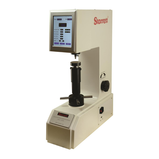
USB data storage. The 3831 is suitable for testing hardness of carbon steel, alloy steel, cast iron, non ferrous metals and engineering plastics. - Page 4 Basic configuration and structure Fig.4-2 1.Top Cover 2.Back Cover 3. Touch Screen 4.Indenter Screw 5.Indenter 6.Anvil(test table) 7.Dust Cover 8.Elevating Wheel 9.Power Switch 10.USB Port 11.Leveling Feet(4) 12.Indenter Protector Uncrating the hardness tester Cut the straps on the packing crate, remove the screws on the bottom plate of the box and remove off the upper body of the crate.
- Page 5 To obtain the maximum workable height you will need to machine a hole in the stand to allow the elevating screw to pass through without interference. See drilling dimension below: Installation of the weights: Remove the weight group out of the accessories kit and clean them thoroughly.
-
Page 6: Setting Parameters
Setting Parameters: All can be set using the intuitive touch screen display. Main Touch Screen Interface Entering Operation Name / Item ID: Touch the screen to the right of “NAME” and/ or “ID#” and the alpha-numeric interface will be shown on the display as shown below. Use the touch screen to enter the information and then touch the “OK”... - Page 7 For testing round parts only! Entering Diameter of Curvature: Touch the screen to the right of “Diameter of Curvature” and the numeric interface will be shown on the display as shown below Use the touch screen to enter the diameter of your part in millimeters(mm) and then touch the “OK”...
- Page 8 Entering Hardness Scale: Touch the screen to the right of “HARDNESS SCALE” and the scale selection screen will be shown as below: Use the touch screen to choose your desired hardness scale. Once selected, the display will change back to the main testing screen. Next use the weight selector knob on the right side of the machine and make sure you choose the proper load for the hardness scale chosen.
- Page 9 This is the amount of time the major load is being applied Entering Dwell Time: to the sample. Recommended time is 5 seconds for basic Rockwell. Touch the screen to the right of “DWELL TIME” and the numeric interface will be shown as below.
- Page 10 CALIBRATION: The calibration was set prior to delivery and should not be needed. However due to shipping and movement thereafter you may need to make some slight adjustments. Its advisable that you contact our tech support team for assistance. Call (201) 962-8352 Step 1) Using one of the supplied test blocks, take a minimum of 3 tests and obtain your average.
- Page 11 Step 6) Press SAVE to store your new calibration and this will bring you back to the main testing screen. Step 7) Begin taking tests on your test block and confirm that the above calibration is within tolerance. Always omit the first test result after calibration. If the results are still out of tolerance then you can perform the calibration again.
- Page 12 Seating Your Diamond: IMPORTANT!: To ensure accuracy, mount the indenter by sliding it in the holder as far as possible and then securing the indenter by tightening the set screw finger-tight only. Place HRC test block on the small round anvil and begin by turning the handwheel clockwise until the block just touches the diamond.
-
Page 13: Maintenance And Service
Maintenance and Service When the hardness tester is to be moved or transported, the weights and its assembly MUST be removed from the inside of the machine. Store in the supplied tool kit. When performing any physical adjustments, the power supply must be disconnected. - Page 14 Approximate Hardness Conversion Numbers for Non-Austenitic Steels (Rockwell C Hardness Range) Brinell Hardness Number C Rockwell Superficial Rockwell Number Rockwell Vickers 10-mm 10-mm Knoop A Scale 15-N 30-N 45-N Scleroscope (HV) Standar Carbide 500-gf 60 kgf Scale Scale Scale Scale HardnessD 150kgf d ball...
- Page 15 Approximate Hardness Conversion Numbers for Non-Austenitic Steels (Rockwell B Hardness Range) A Rockwell Superficial Rockwell Number Rockwell B Vickers 10-mm Knoop F Scale 15-T Scale 30-T Scale 45-T Scale 100kgf (HV) Standard 500-gf Scale 60kgf 15-kgf 30-kgf 45-kgf (HRB) ball 60 kgf (HRF) (HR15T)
- Page 16 Weight - Load - Indenter Chart Scale Indentor Type Preliminary Total Typical Applications Symbol Force Force (kgf) (kgf) Spheroconical 98.07 (10) 588.4 (60) Cemented carbides, thin steel, and shallow case hardened steel Diamond 1/16” Carbide Ball 98.07 (10) 980.7 (100) Copper alloys, soft steels, aluminum alloys, malleable iron, etc.
- Page 17 Round Correction Factors Corrections to be added to test results in the following scales for various diameter parts. Corrections to be added to Rockwell C, A and D values Diameter of Convex Cylindrical Surfaces Hardness ¼” 3/8” ½” 5/8” ¾” 7/8”...
- Page 18 Minimum Thickness Requirements Minimum allowable thickness for a corresponding hardness in the respective scales Minimum Minimum Rockwell Rockwell Rockwell Superficial Superficial Superficial Superficial Superficial Superficial Thickness Thickness Inch 0.006 0.15 … … … … … … … … … 0.008 0.20 …...
Need help?
Do you have a question about the 3831 and is the answer not in the manual?
Questions and answers