
Related Manuals for Elettrotest RMIS 30A/2 RACK


Summary of Contents for Elettrotest RMIS 30A/2 RACK
- Page 1 RMIS USER MANUAL Clicca qui per vedere la versione del manuale in italiano. 07/02/2024 User Manual RMIS 62000641_12A...
- Page 2 RESISTANCE METER Models covered in this manual: Model Code RMIS 30A/2 RACK 99150200 RMIS 3A/2 RACK 99150250 RMIS 3A/2 20K RACK 99150251 This manual is written for RMIS firmware version FW10086 and higher. To consult older manual versions, please contact our support at service@elettrotestspa.it...
- Page 3 Document list: This manual is completed by a list of documents, useful to understand all the features of your Resistance Meter. Scan the QR-code or click on the link to directly download the documents. Documents Description Link QR-code User Manual Latest manual version Manual Datasheet...
- Page 4 SAFETY WARNINGS The manufacturer urges users to read the user manual for our products before installation. The installation must be carried out by qualified technical staff. The non-observance of the warnings in this manual can cause electric shocks, even fatal ones. Please find below some general safety warnings.
- Page 5 DISPOSAL INFORMATION FOR USERS ON THE CORRECT HANDLING OF WASTE ELECTRICAL AND ELECTRONIC EQUIPMENT (WEEE) In reference to European Union directive 2012/19/EU issued on 24 July 2012 and the related national legislation, please note that: • WEEE cannot be disposed of as municipal waste and such waste must be collected and disposed of separately;...
-
Page 6: Table Of Contents
General specifications ....................11 MODELS ............................12 MECHANICAL DRAWINGS ......................12 2.1.1 99150200 RMIS 30A/2 RACK ..................12 2.1.2 99150250 RMIS 3A/2 RACK & 99150251 RMIS 3A/2 20K RACK ........13 NOTES FOR USERS ........................14 EXTERNAL VIEW ..........................14 3.1.1... - Page 7 GENERAL SETTINGS ........................33 7.1.10 SETTINGS MENU ......................34 7.1.11 USER SETTINGS ......................34 7.1.12 OPERATION SETTINGS ....................35 REMOTE SETTINGS ......................... 36 7.1.13 ETHERNET settings ....................... 36 7.1.14 RS 232 settings ......................36 7.1.15 RS485 settings ......................37 USB MENU ............................37 7.1.16 Save Graph ........................
-
Page 8: Introduction
1. INTRODUCTION RMIS is essentially based on the typical principle of resistance meters, that is, on the injection of current on the load to be measured. The resistance measurement is carried out through the ratiometric ratio between the voltage on the load, purified by the alternate power supply component, and the direct component of the current injected on the load. - Page 9 The second method consists in checking the changes in resistance of the material under test (copper, aluminum, etc.) due to the effect of heating and, knowing its relative thermal coefficient, go back to the temperature. The formula normally used, also in relation to specific regulations, is the following for temperatures in degrees centigrade: –...
- Page 10 With FILTER mode (low-medium-high) it is possible to choose the time of response of the instrument, adapting it to the various demands, decreasing the disturbances to the measure caused from the pulsating loads like for example the motors for compressor. RMIS allows the measurement at four wires of the load resistance, which allows to take the measurement on loads far from the instrument and avoiding that itself results faulty.
-
Page 11: General Specifications
1.1.2 General specifications RMIS 30A/2 RMIS 3A/2 RMIS 3A/2 20K Code 99150200 99150250 99150251 Input Voltage Supply 230Vac ± 10% 3 A (1,5A*) 20400 Hz 1,5 A (0,5A*) 20400 Hz 1,5 A (0,5A*) 20400 Hz Current 30 A (15A* ) 20400 Hz 3 A (1.5A* ) 20400 Hz... -
Page 12: Models
30Arms 483x430x178mm 500Vrms 2, 20, 200, 2000 RACK 4U-19” 3A/2/R 99150250 18Kg 3Arms 483x430x178mm 500Vrms 20, 200, 2000, 2k RACK 4U-19” 3A/2/20k R 99150251 18Kg 3Arms 483x430x178mm 2. MECHANICAL DRAWINGS 2.1.1 99150200 RMIS 30A/2 RACK 07/02/2024 User Manual RMIS 62000641_12A... -
Page 13: 99150250 Rmis 3A/2 Rack & 99150251 Rmis 3A/2 20K Rack
2.1.2 99150250 RMIS 3A/2 RACK & 99150251 RMIS 3A/2 20K RACK 07/02/2024 User Manual RMIS 62000641_12A... -
Page 14: Notes For Users
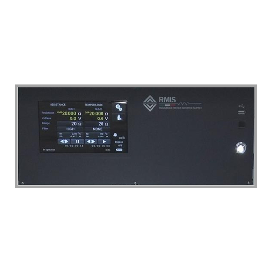
3. NOTES FOR USERS EXTERNAL VIEW 3.1.1 Front Panel RMIS 30A/2 – RMIS 3A/2 - RMIS 3A/2 20K Figure 2.1 Item Name Description Input programming data or options by manipulating touch screen Touch Screen desired one This interface is used for connect data storage to save log USB Type A information Interface... -
Page 15: Rear Panel Rmis 30A/2
3.1.2 Rear Panel RMIS 30A/2 5 6 7 13 14 ETHERNET RS232 RS485 INJECTION NO/NC AUX SIGNAL TEMP RHM1 SENSE FUSE 2,5A LINE 220VAC INJECTION RHM2 SENSE Figure 2.2 Item Name Description Output Sockets These sockets are used to output AC power to the load Input Sockets (30A) These sockets are used to input max 30A power for the load Input Sockets (3A) -
Page 16: Rear Panel Rmis 3A/2 - Rmis 3A/2 20K
3.1.3 Rear Panel RMIS 3A/2 - RMIS 3A/2 20K 5 6 7 13 14 ETHERNET RS232 RS485 INJECTION NO/NC AUX SIGNAL TEMP RHM1 SENSE FUSE 2,5A LINE 220VAC INJECTION RHM2 SENSE Item Name Description Output Sockets These sockets are used to output AC power to the load Input Sockets (3A) These sockets are used to input max 3A power for the load Input Sockets (1,5A) -
Page 17: Installation
Do not return the product to the factory without obtaining the prior Return Merchandise Authorization (RMA) acceptance from ELETTROTEST SPA. 4.1.2 USER PREPARATION After placing the instrument in the dedicated rack compartment,... -
Page 18: Wirings For Single-Phase Motors
WIRINGS FOR SINGLE-PHASE MOTORS 4.1.4 2-WIRE MEASURE OF A SINGLE WINDING If high measurement precision is not required, the SENSE terminals can be short-circuited with the corresponding INJECTION terminals. This configuration is advisable only with loads of high internal resistance (2000 ohm f.s.), in which case the resistance of the wiring becomes negligible. -
Page 19: 4-Wire Measure Of A Single Winding
4.1.5 4-WIRE MEASURE OF A SINGLE WINDING In this configuration the measurement is not influenced by the resistance of the connections to the load. INPUT 1PH LOAD Do not short-circuit the two input lines, it is mandatory to have only one input line connected. Note: The measurement can be carried out indifferently in channel 1 or channel 2 of the RMIS (RHM1 or RHM2) 07/02/2024... -
Page 20: 2-Wire Measure Of A Two Different Windings
4.1.6 2-WIRE MEASURE OF A TWO DIFFERENT WINDINGS If high measurement precision is not required, the SENSE terminals can be short-circuited with the corresponding INJECTION terminals. This configuration is advisable only with loads of high internal resistance (2000 ohm f.s.), in which case the resistance of the wiring becomes negligible. -
Page 21: 4-Wire Measure Of A Two Different Windings
4.1.7 4-WIRE MEASURE OF A TWO DIFFERENT WINDINGS In this configuration the measurement is not influenced by the resistance of the connections to the load. INPUT 1PH LOAD Do not short-circuit the two input lines, it is mandatory to have only one input line connected. 07/02/2024 User Manual RMIS 62000641_12A... -
Page 22: Wirings For Three-Phase Motors
WIRINGS FOR THREE-PHASE MOTORS 4.1.8 2-WIRE MEASURE OF A SINGLE WINDING If high measurement precision is not required, the SENSE terminals can be short-circuited with the corresponding INJECTION terminals. This configuration is advisable only with loads of high internal resistance (2000 ohm f.s.), in which case the resistance of the wiring becomes negligible. -
Page 23: 4-Wire Measure Of A Single Winding
4.1.9 4-WIRE MEASURE OF A SINGLE WINDING In this configuration the measurement is not influenced by the resistance of the connections to the load. INGRESSO 3F CARICO TRIFASE Do not short-circuit the two input lines, it is mandatory to have only one input line connected. Note: The wiring will not change if the motor is connected as Δ. -
Page 24: 2-Wire Measure Of A Two Different Windings
4.1.10 2-WIRE MEASURE OF A TWO DIFFERENT WINDINGS Note: This measurement is not possible with the delta connection or if the star point of the motor is not reachable. If high measurement precision is not required, the SENSE terminals can be short-circuited with the corresponding INJECTION terminals. -
Page 25: 4-Wire Measure Of A Two Different Windings
4.1.11 4-WIRE MEASURE OF A TWO DIFFERENT WINDINGS Note: This measurement is not possible with the delta connection or if the star point of the motor is not reachable. In this configuration the measurement is not influenced by the resistance of the connections to the load. -
Page 26: Remote Control And External Connection
5. REMOTE CONTROL AND EXTERNAL CONNECTION RMIS can be remotely controlled via RS232, RS485 or ETHERNET communication port. Please refer to the protocol manual for details. SERIAL REMOTE CONTROL 5.1.1 RS232 Serial cable Use a serial cable according to the standard defined in the figure below. WIRING CONNESSION RMIS DB9 Poles Female... -
Page 27: Accessories
6. ACCESSORIES 6.1.1 99150200 RMIS 30A/2 Description FUSE 5X20 CF - 2.5A FAST FUSE 10X38 CARTRIDGE 300mA 600VAC/VDC FUSE 10X38 AM-4A USB KEY-KIT 6.1.2 99150250 RMIS 3A/2 & 99150250 RMIS 3A/2 20K Description FUSE 5X20 CF - 2.5A FAST FUSE 10X38 CARTRIDGE 300mA 600VAC/VDC FUSE 10X38 AM-4A FUSE 10X38 AM-2A USB KEY-KIT... -
Page 28: Local Operation
7. LOCAL OPERATION The product can support local operation or remote operation enabled via complete communication interfaces, such as RS232, RS485, Ethernet. In this section, the local operation enabled via the 7- inch touch screen on the front panel will be described. The product is configured for local operation when it is turned on. -
Page 29: Resistance Page
7.1.3 RESISTANCE PAGE 4 5 6 9 10 11 12 13 14 15 16 17 Figure 7.3 Item Name Description Information bar Displays information for the user Start and Stop the test for the RHM1 channel resistance RHM1 START button measurement RHM1 TEST button Enable or disable the auxiliary output of RHM1... -
Page 30: Resistance Range Selection
NOTICE: if the RHM1 or RHM2 Start button is pressed without first having set the initial resistance and temperature values (see point 7.2.5), a CALCULATION ERROR message will appear Figure 7.4 7.1.4 RESISTANCE RANGE SELECTION By clicking on the button , allows to access the Range settings page 1 2 3 4 5 6 NOTICE:... -
Page 31: Filter Level Selection
7.1.5 FILTER LEVEL SELECTION By clicking on the button , allows to access the Filter settings page 1 2 3 4 5/6 NOTICE: this description is the same for RHM2 channel Figure 7.6 Item Name Description NONE button No filtering (only to remove PWM) LOW button Allows select LOW FILTER level (HW filtering) MEDIUM button... -
Page 32: Initial Load Settings Page
7.1.7 INITIAL LOAD SETTINGS PAGE By clicking on the button , allows to access the Initial Settings page for temperature and resistance NOTICE: this description is the same for RHM2 channel Figure 7.8 Item Name Description Allows to come back to the previous page with the new initial Confirm button load settings Allows to come back to the previous page without any... -
Page 33: Temperature Measurement
TEMPERATURE MEASUREMENT 7.1.9 TEMPERATURE PAGE 3 4 5 Figure 7.10 Item Name Description RHM2 ∆T Display the trend of temperature variation of RHM2 channel RHM1 ∆T Display the trend of temperature variation of RHM1 channel Clear button Clear the temperatures diagrams + button Zoom in (only for “Y”... -
Page 34: Settings Menu
7.1.10 SETTINGS MENU Figure 7.12 Item Name Description Home button Allows to come back to the main page Advanced Command Allows to access the advanced command mode page Mode User Setting button Allows to access the User Settings page Remote Setting button Allows to access the Remote Settings page Operation Setting button Allows to access the Operation Settings page... -
Page 35: Operation Settings
Item Name Description Home button Allows to come back to the main page Sound Feedback button Allows to enable o disable audible feedback Brightness button Allows to change the touch screen brightness Language button Allows to change the menu language Theme button Allows to change the interface colors 7.1.12 OPERATION SETTINGS... -
Page 36: Remote Settings
REMOTE SETTINGS By clicking on the general REMOTE SETTING button , allows to access the settings menu page, this page depends from the serial output (ETHERNET / RS232 / RS485), down there is a table with the available protocol in the different interface PORT RS232 RS485... -
Page 37: Rs485 Settings
7.1.15 RS485 settings USB MENU By clicking on the button , allows to access the USB menu. Item Name Description Home Button Allows to come back to the main page Save Graph button Allows to save the graph into the USB-KEY Saving Data button Allows to save the log file of the operations into the USB key 07/02/2024... -
Page 38: Save Graph
Note : It is possible to select a name both for the log and the graphs before saving them. 7.1.16 Save Graph Clicking on it is possible to save the graph shown in the display in that moment. The saving operation least for about 40 seconds, during that time the display will display a loading bar. -
Page 39: Application Warning
8. APPLICATION WARNING START-UP WARNINGS Decoupling capacitor can cause problems during the startup of an inverter supplied load/motor (typical brushless sensorless), so it’s very important to start always with BYPASS ON. When RMIS is plug connected with supply line and standby is off (Panel off), BYPASS normal condition is ON, in order to have possibilities to have instrument on system without any problem. -
Page 40: Instrument Calibration
9. INSTRUMENT CALIBRATION From firmware revision v.10086 it is possible to set a Kuser parameter that adjust the read value of the RMIS multiplying it for this Kuser. There is one Kuser for each of the 4 ranges, so there is four Kuser for each RHM channel. Every Kuser is active only if it’s range is selected. -
Page 41: Calibration Page
CALIBRATION PAGE Typing “__UCALIBK” into the Advanced command mode, it is possible to access the calibration menu. To calibrate the RMIS it is necessary to wire the injection and sense terminals of the instrument to a resistor with a well-known value. Select the correct range based on the measured resistance and then correct the RMIS’... -
Page 42: Remote Control
10. REMOTE CONTROL 10.1 MODBUS PROTOCOLS There are two modbus protocols available for the RMIS: • MODBUS RTU (For both serial and LAN connections) • MODBUS TCP (only for LAN connections) both ModBus RTU and ModBus TCP has the same Input Registers and Holding Registers. Standard configurations for the ModBus protocol are: •... - Page 43 10.3 HOLDING REGISTER Variable Address Range Factory Description value Not used Elettrotest use Address Mod 1-250 1 (*) ModBus Address Address IP1 192 (*) Address IP2 168 (*) Address IP3 1 (*) Address IP4 1 (*) Subnet mask 1 255 (*)
- Page 44 Filtro RHM2 b0-b3 0 (*) Filter Level RHM2 0 = (0b00000000) = Filter = None 1 = (0b00000001) = Filter = Low 2 = (0b00000010) = Filter = Medium 3 = (0b00000011) = Filter = High R0 RHM1 dec 0.999 Decimal part R0 RHM1 (expressed in thousands) R0 RHM1 int 0.20000...
- Page 45 10.4 INPUT REGISTERS Variable Address Range Description Not used Elettrotest use RES Range base 0 .. 20000 Resistance Range base RHM1 RHM1 RES Range base 0 .. 20000 Resistance Range base RHM2 RHM2 VOLT base 0 .. 10000 5000 Full scale voltage value x10 RES 1 0 ..
-
Page 46: Guarantee
Such document must always accompany the apparatus in case of periodic verification. 12. REVISION INDEX Elettrotest Spa is committed to a program of continuous improvement of products and information to the customer. Therefore, the company reserves the right to make changes to the documentation and specifications without notice and assumes no responsibility for any incorrect information. - Page 47 RMIS MANUALE UTENTE Click here to see the english version of this manual. 07/02/2024 User Manual RMIS 62000641_12A...
- Page 48 Modelli di RESISTANCE METER trattati in questo manuale: Modello Codice RMIS 30A/2 RACK 99150200 RMIS 3A/2 RACK 99150250 RMIS 3A/2 20K RACK 99150251 Questo manuale è scritto per le versioni firmware FW10086 e successive. Per consultare manuali di versioni precedenti, contatta il supporto Elettrotest: service@elettrotestspa.it...
- Page 49 Lista Documenti: Questo manuale è completato da un elenco di documenti utili per comprendere tutte le caratteristiche del vostro RMIS. Scansiona il QR-code o clicca sul link per scaricare direttamente i documenti di cui hai bisogno. Documents Description Link QR-code User Manual Ultima versione manuale utente Manual...
- Page 50 AVVERTENZE PER LA SICUREZZA Il costruttore raccomanda di leggere attentamente il manuale d’istruzione dei suoi prodotti prima di procedere con la loro installazione. L’installazione deve essere eseguita da personale tecnico qualificato. L’inosservanza delle raccomandazioni riportate in questo manuale può causare shock elettrici anche mortali. Di seguito sono riportate alcune avvertenze generali in merito alla sicurezza.
- Page 51 SMALTIMENTO INFORMAZIONE AGLI UTENTI PER IL CORRETTO TRATTAMENTO DEI RIFIUTI DI APPARECCHIATURE ELETTRICHE ED ELETTRONICHE (RAEE) In riferimento alla Direttiva 2012/19/UE del Parlamento Europeo e del Consiglio del 24 luglio 2012 e alle relative normative nazionali di attuazione (D.Lgs. 49/2014), Vi informiamo che: •...
- Page 52 INDICE INTRODUZIONE ..........................8 CARATTERISTICHE PRINCIPALI ....................8 1.1.1 Informazioni generali ..................... 8 1.1.2 Specifiche generali ....................... 11 MODELLI ..........................12 DISEGNI MECCANICI ........................12 2.1.1 99150200 RMIS 30A/2 ....................12 2.1.2 99150250 RMIS 3A/2 & 99150251 RMIS 3A/2 20K ............. 13 NOTE PER L’UTENTE ........................
- Page 53 7.3.1 PAGINA TEMPERATURA ....................33 IMPOSTAZIONI GENERALI....................33 7.4.1 IMPOSTAZIONI UTENTE ....................34 7.4.2 PAGINA IMPOSTAZIONI UTENTE .................. 34 7.4.3 PAGINA IMPOSTAZIONI OPERATIVE ................35 IMPOSTAZIONI REMOTE ...................... 36 7.5.1 Impostazioni ETHERNET ....................36 7.5.2 Impostazioni RS 232 ..................... 36 7.5.3 Impostazioni RS485 ......................
-
Page 54: Introduzione
INTRODUZIONE L'RMIS si basa essenzialmente sul principio tipico dei misuratori di resistenza, e cioè, sulla iniezione di corrente sul carico da misurare. La misura di resistenza viene effettuata tramite il rapporto raziometrico tra la tensione sul carico, depurata dalla componente alternata di alimentazione, e la componente continua della corrente iniettata sul carico. - Page 55 Il secondo metodo consiste nel controllare le variazioni di resistenza del materiale in prova (rame, alluminio, ecc.) per effetto del riscaldamento e, conoscendone il relativo coefficiente termico, risalire alla temperatura. La formula normalmente usata, anche in relazione a specifiche normative, è la seguente per temperature in gradi centigradi: (R2-R1) t = ----------- (+t1)-(t2-t1)
- Page 56 RMIS consente la misurazione su quattro fili della resistenza di carico, il che consente di eseguire la misurazione su carichi lontani dallo strumento ed evitare che si verifichi un errore. Questo tipo di misura richiede solo tre ulteriori connessioni (spine di contatto SENSE) di sezione ridotta. RMIS comunica con qualsiasi computer tramite una porta seriale RS232 o RS485 e una porta LAN;...
-
Page 57: Specifiche Generali
1.1.2 Specifiche generali RMIS 30A/2 RMIS 3A/2 RMIS 3A/2 20K Codice 99150200 99150250 99150251 Tensione in ingresso 230Vac ± 10% 3 A (1,5A*) 20400 Hz 1,5 A (0,5A*) 20400 Hz 1,5 A (0,5A*) 20400 Hz Correnti 30 A (15A* ) 20400 Hz 3 A (1.5A* ) 20400 Hz... -
Page 58: Modelli
MODELLI Modello Codice Limiti di misura Scale di resistenza Dimensioni Peso 500Veff 2, 20, 200, 2000 RACK 4U-19” 30A/2/R 99150200 22Kg 30Aeff 483x430x178mm 500Veff 2, 20, 200, 2000 RACK 4U-19” 3A/2 99150250 18Kg 3Aeff 483x430x178mm 500Veff 20, 200, 2000, 20k RACK 4U-19”... -
Page 59: 99150250 Rmis 3A/2 & 99150251 Rmis 3A/2 20K
2.1.2 99150250 RMIS 3A/2 & 99150251 RMIS 3A/2 20K 07/02/2024 User Manual RMIS 62000641_12A... -
Page 60: Note Per L'utente
NOTE PER L’UTENTE VISTA ESTERNA 3.1.1 Pannello frontale RMIS 30A/2 – RMIS 3A/2 - RMIS 3A/2 20K Figura 2.1 Item Tipologia Descrizione Questo touch screen permette di interagire con lo strumento in Display 7” maniera semplice ed intuitiva. Porta Interfaccia per il collegamento di una chiavetta di storage per USB Tipo A memorizzazione log. - Page 61 5 6 7 5 6 7 13 14 13 14 ETHERNET RS232 RS485 INJECTION NO/NC TEMP AUX SIGNAL RHM1 SENSE FUSE 2,5A LINE 220VAC INJECTION RHM2 SENSE Figure 2.2 Figura 2.2 N° Tipologia Descrizione Boccole OUTPUT Vengono utilizzate per alimentare il carico Vengono utilizzate per alimentare il carico con una corrente massima di Boccole INPUT 30A Boccole INPUT 3A...
-
Page 62: Pannello Retro Rmis 3A/2 & Rmis 3A/2 20K
3.1.3 Pannello retro RMIS 3A/2 & RMIS 3A/2 20K 5 6 7 13 14 ETHERNET RS232 RS485 INJECTION NO/NC AUX SIGNAL TEMP RHM1 SENSE FUSE 2,5A LINE 220VAC INJECTION RHM2 SENSE Item Name Description Boccole Output Vengono usate per alimentare il carico Boccole d’ingresso (3A) Vengono utilizzate per alimentare il carico con una corrente massima di 3A Vengono utilizzate per alimentare il carico con una corrente massima di... -
Page 63: Installazione
In caso di danni, presentare immediatamente un reclamo al corriere. Non restituire il prodotto in fabbrica senza aver ottenuto l'autorizzazione preventiva per l'autorizzazione alla restituzione della merce (RMA) da ELETTROTEST SPA. 4.1.2 Preparazione Dopo aver posizionato lo strumento nel vano rack dedicato, sul pannello posteriore collegare un cavo di alimentazione 2P + T di dimensioni adeguate (3x1,5mm2 consigliato) utilizzando la presa fornita con lo strumento. -
Page 64: Collegamenti Motore Monofase
COLLEGAMENTI MOTORE MONOFASE 4.1.4 MISURA DI UN SINGOLO AVVOLGIMENTO A 2 FILI Nel caso in cui non sia richiesta una elevata precisione nella misura, i morsetti di SENSE possono essere cortocircuitati con i corrispondenti morsetti di INJECTION. Questa configurazione è consigliabile solo con carichi di elevata resistenza interna (2000 ohm f.s.), divenendo in tal caso trascurabile la resistenza dei cablaggi. -
Page 65: Misura Di Un Singolo Avvolgimento A 4 Fili
4.1.5 MISURA DI UN SINGOLO AVVOLGIMENTO A 4 FILI In questa configurazione la misura non è influenzata dalla resistenza dei collegamenti al carico. INPUT 1PH CARICO MONOFASE È obbligatorio connettere una sola linea di ingresso, NON cortocircuitare le due linee di ingresso per nessun motivo Nota: La misura può... -
Page 66: Misura Di Due Avvolgimenti A 2 Fili
4.1.6 MISURA DI DUE AVVOLGIMENTI A 2 FILI Nel caso in cui non sia richiesta una elevata precisione nella misura, i morsetti di SENSE possono essere cortocircuitati con i corrispondenti morsetti di INJECTION. Questa configurazione è consigliabile solo con carichi di elevata resistenza interna (2000 ohm f.s.), divenendo in tal caso trascurabile la resistenza dei cablaggi. -
Page 67: Misura Di Due Avvolgimenti A 4 Fili
4.1.7 MISURA DI DUE AVVOLGIMENTI A 4 FILI In questa configurazione la misura non è influenzata dalla resistenza dei collegamenti al carico. INPUT 1PH CARICO MONOFASE È obbligatorio connettere una sola linea di ingresso, NON cortocircuitare le due linee di ingresso per nessun motivo 07/02/2024 User Manual RMIS 62000641_12A... -
Page 68: Collegamenti Motore Trifase
COLLEGAMENTI MOTORE TRIFASE 4.1.8 MISURA DI UN SINGOLO AVVOLGIMENTO A 2 FILI Nel caso in cui non sia richiesta una elevata precisione nella misura, i morsetti di SENSE possono essere cortocircuitati con i corrispondenti morsetti di INJECTION. Questa configurazione è consigliabile solo con carichi di elevata resistenza interna (2000 ohm f.s.), divenendo in tal caso trascurabile la resistenza dei cablaggi. -
Page 69: Misura Di Un Singolo Avvolgimento A 4 Fili
4.1.9 MISURA DI UN SINGOLO AVVOLGIMENTO A 4 FILI In questa configurazione la misura non è influenzata dalla resistenza dei collegamenti al carico. INGRESSO 3F CARICO TRIFASE È obbligatorio connettere una sola linea di ingresso, NON cortocircuitare le due linee di ingresso per nessun motivo Note: Il cablaggio non cambierà... -
Page 70: Misura Di Due Avvolgimenti A 2 Fili
4.1.10 MISURA DI DUE AVVOLGIMENTI A 2 FILI Nel caso in cui non sia richiesta una elevata precisione nella misura, i morsetti di SENSE possono essere cortocircuitati con i corrispondenti morsetti di INJECTION. Questa configurazione è consigliabile solo con carichi di elevata resistenza interna (2000 ohm f.s.), divenendo in tal caso trascurabile la resistenza dei cablaggi. -
Page 71: Misura Di Due Avvolgimenti A 4 Fili
4.1.11 MISURA DI DUE AVVOLGIMENTI A 4 FILI Nota: Questa misura non è possibile con il collegamento a triangolo e se il centro stella del motore non è raggiungibile. In questa configurazione la misura non è influenzata dalla resistenza dei collegamenti al carico. INGRESSO 3F CARICO TRIFASE... -
Page 72: Controllo Remoto
CONTROLLO REMOTO RMIS può essere controllato a distanza tramite porta di comunicazione RS232, RS485 o ETHERNET. Per i dettagli, consultare il manuale del protocollo CONTROLLO SERIALE 5.1.1 Cavo serial RS232 Il cavo seriale utilizza lo standard definito nella figura sottostante WIRING CONNESSION RMIS DB9 Poles Female... -
Page 73: Accessori
ACCESSORI 6.1.1 99150200 RMIS 30A/2 Descrizione Q.tà FUSIBILE 5X20 CF - 2.5A FAST FUSIBILE 10X38 CARTRIDGE 300MA 600VAC/VDC FUSIBILE 10X38 AM-4A KIT CHIAVETTA USB 6.1.2 9915250 RMIS 3A/2 & 99150251 RMIS 3A/2 20K Descrizione Q.tà FUSIBILE 5X20 CF - 2.5A FAST FUSIBILE 10X38 CARTRIDGE 300MA 600VAC/VDC FUSIBILE 10X38 AM-4A FUSIBILE 10X38 AM-2A... -
Page 74: Comandi Locale
COMANDI LOCALE RMIS può supportare il funzionamento locale o il funzionamento remoto abilitato tramite interfacce di comunicazione complete, come RS232, RS485, Ethernet. In questa sezione verrà descritta l'operazione locale abilitata tramite il touchscreen da 7 pollici sul pannello frontale. Il prodotto è configurato per il funzionamento locale quando è... -
Page 75: Pagina Resistenza
7.1.3 PAGINA RESISTENZA 4 5 6 9 10 11 12 13 14 15 16 17 Figura 7.3 N° Nome Descrizione Barra informazioni Visualizza le informazioni per l’utilizzatore Avvia e arresta la prova per la misurazione della resistenza sul Tasto START RHM1 canale RHM1 Tasto TEST RHM1 Abilita e disabilita l’uscita ausiliaria di RHM1... -
Page 76: Selezione Portata Resistenza
AVVISO: se si avvia il test di misurazione per il canale RHM1 o RHM2 senza aver prima impostato i valori iniziali di resistenza e temperatura (vedere punto 7.2.5), verrà visualizzato un messaggio “ERRORE CALCOLO” Figura 7.4 7.1.4 SELEZIONE PORTATA RESISTENZA Cliccando sul tasto , si accede alla pagina per la selezione della portata di resistenza... -
Page 77: Selezione Livello Filtraggio Misura
7.1.5 SELEZIONE LIVELLO FILTRAGGIO MISURA Cliccando sul tasto , si accede alla pagina per la selezione del livello di filtraggio della misura di resistenza 1 2 3 4 5/6 AVVISO: Questa descrizione è valida anche per il canale RHM2 Figura 7.6 N°... -
Page 78: Pagina Impostazioni Di Settaggio Iniziale
7.1.7 PAGINA IMPOSTAZIONI DI SETTAGGIO INIZIALE Cliccando sul tasto , si accede alla pagina per le impostazioni del settaggio iniziale della temperatura e resistenza AVVISO: Questa descrizione è valida anche per il canale RHM2 Figura 7.8 N° Nome Descrizione Consente di tornare alla pagina precedente mantenendo Tasto “✓”... -
Page 79: Misura Della Temperatura
MISURA DELLA TEMPERATURA 7.1.9 PAGINA TEMPERATURA 3 4 5 Figura 7.10 N° Nome Descrizione Mostra l’andamento della variazione di temperatura ∆T nel RHM2 ∆T canale RHM2 Mostra l’andamento della variazione di temperatura ∆T nel RHM1 ∆T canale RHM1 Clear button Pulisce il grafico + button Zoom in (solo per asse “Y”)*... -
Page 80: Impostazioni Utente
7.1.10 IMPOSTAZIONI UTENTE Figure 7.12 N° Nome Descrizione Pulsante Home Permette di tornare alla schemata principale Pulsante comandi Permette di accedere ai comandi avanzati avanzati Pulsante impostazioni Permette di accedere alle impostazioni utente utente Pulsante impostazioni Permette di accedere alle impostazioni remote remote Pulsante impostazioni di Permette di accedere alle impostazioni operazionali... -
Page 81: Pagina Impostazioni Operative
N° Nome Descrizione Tasto HOME Consente di tornare alla schermata iniziale Tasto Consente di abilitare o disabilitare il feedback acustico FEEDBACK SONORO Tasto LUMINOSITA’ Consente di variare la luminosità del display Tasto LINGUA Consente di modificare la lingua utente Tasto TEMA Consente di cambiare I colori dell’interfaccia utente 7.1.12 PAGINA IMPOSTAZIONI OPERATIVE Premendo il pulsante... -
Page 82: Impostazioni Remote
IMPOSTAZIONI REMOTE Cliccando sul pulsante REMOTE SETTING , permette di accedere alla pagina del menu impostazioni remote, questa pagina dipende dall'uscita seriale (ETHERNET / RS232 / RS485), in basso c'è una tabella con il protocollo disponibile nelle diverse interfacce. PORT RS232 RS485 ✓... -
Page 83: Impostazioni Rs485
7.1.15 Impostazioni RS485 SALVATAGGIO SU CHIAVETTA USB Cliccando sul tasto , è possibile accedere alla pagina di salvataggio delle misure su chiavetta USB. N° Nome Descrizione Pulsante Home Permette di tornare al menu principale Pulsante Save Graph Permette di salvare il grafico mostrato nell’USB Pulsante Saving Data Permette di salvare il file log delle misure nell’USB 07/02/2024... -
Page 84: Salvataggio Grafico
Nota : è possibile selezionare il nome dei file salvati su chiavetta USB sia per il salvataggio dei grafici, sia per il salvataggio del file log. 7.1.16 Salvataggio Grafico Cliccando su è possibile salvare il grafico mostrato in quel momento nel display. L’operazione di salvataggio del grafico su chiavetta USB avrà... -
Page 85: Salvataggio Dati
7.1.17 Salvataggio Dati Cliccando su è possibile iniziare il salvataggio dei dati nella chiavetta USB in un file log. Il file log è un file di testo che conterrà tutti i valori mostrati a display. Successivamente all’inserimento da parte dell’utente del nome del file, l’RMIS inizierà a salvare i valori letti da quel momento in poi. -
Page 86: Attenzioni Nell'applicazione
ATTENZIONI NELL’APPLICAZIONE FASE DI AVVIAMENTO I condensatori di disaccoppiamento possono essere un problema durante le fasi di start up dei carichi comandati ad inverter (tipico un brushless sensorless), quindi durante l’avvio è importante impostare il BYPASS=ON. Proprio per questo lo strumento prevede di avviare lo strumento con BYPASS ON (basta che sia alimentato), questo anche quando il pannello è... -
Page 87: Bypass Automatico
BYPASS AUTOMATICO BYPASS AUTO può aiutare a semplificare il test Con EUT ACCESO >> BYPASS ON (prima dell’ON) Con INIZIO MISURA >> BYPASS OFF (prima della misura) CALIBRAZIONE STRUMENTO Dalla revisione firmware v.10086 è possibile impostare un parametro Kuser che regola il valore letto dell'RMIS moltiplicandolo per questo Kuser. -
Page 88: Pagina Di Calibrazione Strumento
PAGINA DI CALIBRAZIONE STRUMENTO Digitando “__UCALIBK” nell’ è possibile accedere al menù di calibrazione. Per calibrare l'RMIS è necessario collegare i terminali di iniezione e sense dello strumento ad un resistore di valore noto. Selezionare l'intervallo corretto in base al valore della resistenza misurata e quindi correggere il valore di resistenza visualizzato dell'RMIS con i pulsanti + o –. -
Page 89: Controllo Remoto
CONTROLLO REMOTO PROTOCOLLI MODBUS Sono disponibili due protocolli Modbus per l’RMIS: • MODBUS RTU (sia per connessioni seriali che LAN) • MODBUS TCP (solo per connessioni LAN) sia ModBus RTU che ModBus TCP hanno gli stessi Input Register e Holding Register. Le configurazioni standard per il protocollo ModBus sono: •... - Page 90 12.1 HOLDING REGISTER Variable Address Range Factory Description value Not used Elettrotest use Address Mod 1-250 1 (*) ModBus Address Address IP1 192 (*) Address IP2 168 (*) Address IP3 1 (*) Address IP4 1 (*) Subnet mask 1 255 (*)
- Page 91 0 = (0b00000000) = Filter = None 1 = (0b00000001) = Filter = Low 2 = (0b00000010) = Filter = Medium 3 = (0b00000011) = Filter = High R0 RHM1 dec 0.999 Decimal part R0 RHM1 (expressed in thousands) R0 RHM1 int 0.20000 Int.
-
Page 92: Input Registers
INPUT REGISTERS Variable Address Range Description Not used Elettrotest use RES Range base 0 .. 20000 Resistance Range base RHM1 RHM1 RES Range base 0 .. 20000 Resistance Range base RHM2 RHM2 VOLT base 0 .. 10000 5000 Full scale voltage value x10 RES 1 0 .. -
Page 93: Garanzia
REVISIONE Elettrotest Spa è impegnata in un programma di miglioramento continuo di prodotti e informazioni per il cliente. Pertanto, la società si riserva il diritto di apportare modifiche alla documentazione e alle specifiche senza preavviso e non si assume alcuna responsabilità...
Need help?
Do you have a question about the RMIS 30A/2 RACK and is the answer not in the manual?
Questions and answers