Table of Contents
Advertisement
Advertisement
Table of Contents

Related Manuals for Sennheiser EK 3241 - 08-06


Summary of Contents for Sennheiser EK 3241 - 08-06
- Page 1 EK 500 EK 3241 Instructions for use...
-
Page 2: Table Of Contents
Contents Safety instructions ..............3 Delivery includes ............... 3 The EK 3241 true diversity receiver ........4 Operating controls ..............5 LC display panel ................. 5 Putting the receiver into operation ........6 Connecting the antennas ........... 6 Mounting the receiver into a camcorder ......6 Powering the receiver ............ - Page 3 Thank you for choosing Sennheiser! We have designed this product to give you reliable operation over many years. Over 60 years of accumulated expertise in the design and manufacture of high-quality electro-acoustic equipment have made Sennheiser a world-leading company in this field.
-
Page 4: Safety Instructions
Safety instructions Please read these instructions carefully and completely before using the receiver. Make these instructions easily accessible to all users at all times. Always include these instructions when passing the receiver on to third parties. Never open electronic units! If units are opened by customers in breach of this instruction, the warranty becomes null and void. -
Page 5: The Ek 3241 True Diversity Receiver
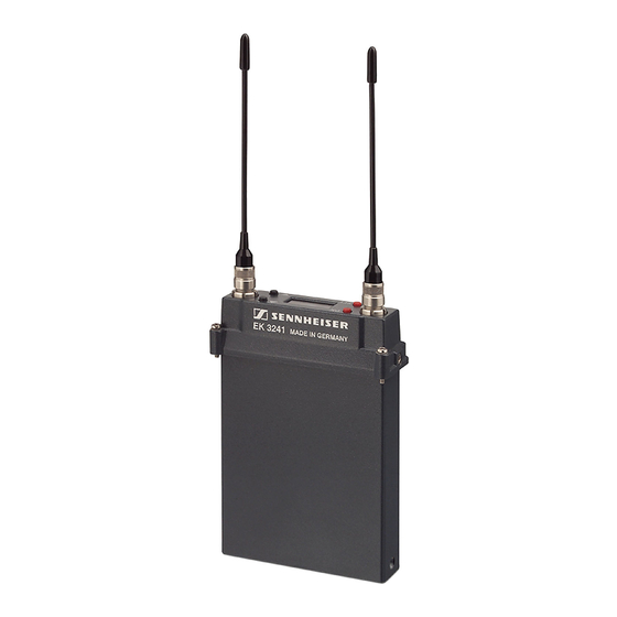
The EK 3241 true diversity receiver The EK 3241 is a miniature true diversity receiver designed for use with digital ENG camcorders. It can be inserted into the slot-in facility of e.g. Ikegami, Panasonic, Sony or Thomson camcorders without any additional connecting cables being required. -
Page 6: Operating Controls
LC display panel button (Down) button (UP) Antenna socket, diversity section B LC display panel “RF” – appears when an RF signal is being received 8-step level display for received RF signal Numeric display 8-step level display for received audio signal... -
Page 7: Putting The Receiver Into Operation
Screw the antennas tight. Mounting the receiver into a camcorder The receiver can be inserted into the slot-in facility of most professional camcorders. Suitable mounting kits are avail- able as accessories from your Sennheiser partner. Mounting kits are available for the following camcorder types (see “Accessories”... -
Page 8: Powering The Receiver
25-pin connector securely connects. Screw receiver (from above) to the mounting frame. Powering the receiver The receiver can be powered from three different power sources: Power source Notes on operation Camcorder with mounting kit See page 6 Camcorder with... -
Page 9: Using The Receiver
The standard display is shown on the LC display panel Note: The receiver can only be switched off when the lock mode is deactivated (see “Activating/deactivating the lock mode – Loc” on page 18). To switch the receiver off,... -
Page 10: The Operating Menu
( ) or changes to the next parameter ( ) Selection mode Changes to the previous menu ( ) or changes to the next menu ( ) Setting mode Increases ( ) or reduces ( ) the setting of the selected... -
Page 11: Working With The Operating Menu
The operating menu has three modes: Display mode In display mode, you can display the current menu settings one after the other – even when the lock mode is activated. Selection mode In selection mode, you can select the menu whose setting you want to change. - Page 12 Displaying the menu settings in display mode In display mode, and with the lock mode activated, you can display the current menu settings one after the other (see “Overview of the operating menu” on page 14). Press the button or the...
- Page 13 Exiting the selection mode and returning to the standard display *) If the receiver is inserted into the slot-in facility of a camcorder, the “PHonE“ menu is deactivated (see page 23). Changing to the setting mode of a selected menu...
- Page 14 The display then returns to selection mode. Cancelling an entry Select the “ESc” menu to exit the selection mode and to return to the standard display. When in the selection or setting mode, briefly pressing...
-
Page 15: Overview Of The Operating Menu
Overview of the operating menu Deactivate the lock mode before adjusting the settings (see “Activating/deactivating the lock mode – Loc” on page 18). Pressing the ON/OFF button will cancel your entry (ESC function) and return you to the display mode. - Page 16 BAt.tr StorEd rESEt rSt. rSt. Loading the Security check YES, no factory-preset “reset” = YES, default settings Receiver loads factory-preset default settings, standard display appears “reset” = no, reset is cancelled Loc. Loc. Setting the Current setting Loc.
-
Page 17: Adjustment Tips For The Operating Menu
Adjusting the headphone volume – PHonE If you operate the receiver with a modified version of the GA 3041-C slot-in housing (see page 23), you can adjust the headphone volume via the “PHonE” menu. The volume can be adjusted between 0 and 126. -
Page 18: Selecting The Frequencies To Be Stored In The
(DOWN) for more than three seconds will switch the squelch off. “Sql.off” appears on the display. If no RF signal is being received, hissing noise will occur. This setting is for test purposes only. Activating/deactivating the automatic receiver switch-on/off via the camcorder –... -
Page 19: Selecting The Standard Display - Disp
Selecting the standard display – dISP Via the “dISP” menu, you can select one of the following standard displays: Channel Frequency Battery status “CHAn” “FrEq” “BAt.tr” The selected standard display is shown after switch-on, after the parameters have been displayed for 15 seconds in display mode. -
Page 20: Care And Maintenance
Care and maintenance Water can damage the electronics of the CAUTION! receiver! Water entering the housing of the receiver can cause a short-circuit and damage the electronics. Only use a slightly damp cloth to clean the receiver. Do not use any solvents or cleansing... -
Page 21: Adjusting The Squelch Threshold – Squelh
Increase the distance overmodulated between transmitter and receiver (see page 21) If a problem occurs that is not listed in the above table or if the problem cannot be solved with the proposed solutions, please contact your local Sennheiser agent for assistance. -
Page 22: Recommendations And Tips
...for a long service life of the battery box or accupack Remove the battery box or accupack from the slot-in housing when the receiver will not be used for extended periods of time. Store the battery box or accupack in a cool and dry place. -
Page 23: Additional Information
The EK 3241 operates on the “true diversity” principle: A receiving antenna receives not only the electromagnetic waves which reach it by a direct path, but also the reflections of these waves which are created in the room by walls, windows, ceilings and fittings. When these waves are superimposed, destructive interference occurs, which can also be called “field strength gaps”. -
Page 24: Accessories
075584 with special connectors Operating the EK 3241 with headphones In order to be able to connect headphones to the EK 3241 receiver, you require a modified version of the GA 3041-C slot-in housing (see “Accessories” above). Please contact your Sennheiser Service Partner. -
Page 25: Specifications
/1 kHz) Terminating impedance ≤ 10 kΩ Power supply 4-pin DC socket, electronically balanced, pin 1: ground, pin 4: 10.5 – 18 V Operation with GA 3041-B Power supply 1.8 – 4.8 V (internally DC/DC adjusted to max. 3.2 V) Current consumption approx. -
Page 26: Connector Assignment (Operation With Ga 3041-C)
Radio: ETSI EN 300422-1/-2, Class 2 EMC: ETSI EN 301489-1/-9 FCC: Part 15, Subpart B Canada: RSS 210, RSS 123 Issue 1 Rev. 2 IC: 2099A-EK3241 Connector assignment (operation with GA 3041-C) XLR-3 connector (female), 4-pin DC socket balanced Pin 1: ground... -
Page 27: Manufacturer Declarations
The guarantee is void if the product is manipulated by non-authorised persons or repair stations. In the case of a claim under the terms of this guarantee, send the device, including accessories and sales receipt, to the responsible service partner. To minimise the risk of transport damage, we recommend that the original packaging is used. - Page 28 Sennheiser electronic GmbH & Co. KG 30900 Wedemark, Germany Phone +49 (5130) 600 0 Fax +49 (5130) 600 300 www.sennheiser.com Printed in Germany Publ. 08/06 516549/A01...
Need help?
Do you have a question about the EK 3241 - 08-06 and is the answer not in the manual?
Questions and answers