Table of Contents
Advertisement
Quick Links
Advertisement
Table of Contents

Related Manuals for Sako V780


Summary of Contents for Sako V780
- Page 4 Mini Vector Inverter MANUAL...
- Page 5 Thank you for purchasing the VFD developed by Hangzhou Sako Frequency Technology Co., Ltd. Read and understand the manual before use and forward the manual to the end user. Before use, please read【the safety precautions】carefully. Please keep this manual carefully for consulting if necessary. If you have any doubt, please contact our customer service or technical support, our professional will serve you wholeheartedly.
-
Page 6: Table Of Contents
Contents Chapter 1 Safety Information and Precautions 1.1 Safety Information and Precautions 1.2 Operation Precautions Chapter 2 Product Information 2.1 Designation Rules 2.2 Technical Specification 2.3 Peripheral Electrical Devices and System Configuration Chapter 3 Installation Guide 3.1 Product Size Diagram 3.2 Product Installation Diagram Chapter 4 Wiring Instructions 4.1 Interface and Terminal Instructions... -
Page 7: Chapter 1 Safety Information And Precautions
Chapter 1 Safety Information and Precautions 1.1 Safety Information and Precautions ◇ It is forbidden to use the device near water, corrosive gas, combustible gas, inflammable and explosive materials, otherwise it will cause electric shock, combustion or explosion. ◇ Prohibit the use of this device in places that restrict or prohibit the use of this device, otherwise it may lead to an accident. -
Page 8: Operation Precautions
1.2 Operation Precautios ◇ It must be connected, installed and operated by a professional. ◇ Wiring shall not be connected when the power supply is turned on, otherwise it may cause electrical shock or injury to personnel. ◇ Terminal voltage and polarity must be applied to prevent damage to equipment or injury to personnel. -
Page 9: Chapter 2 Product Information
Chaper 2 Product Information Upon receipt of the goods, please examine the following items carefully: ◇ Whether the type of frequency inverter is correct. ◇ Whether the appearance is damaged. 2.1 Designation Rules Input Level: 1: 1 phase 220V 4: 3 phase 380V Power: 0D75: 0.75KW 1D5: 1.5KW 2D2: 2.2KW... -
Page 10: Technical Specification
2.2 Technical Specifications Adaptable Motor Rated Power Rated Output Model (KW) Current (A) One phase power supply: 220V, 50Hz/60Hz 780-0D75-1 0.75 0.75 780-1D5-1 780-2D2-1 Three phase power supply: 380V, 50Hz/60Hz 780-0D75-4 0.75 0.75 780-1D5-4 780-2D2-4 780-4D0G-4 780-5D5G-4 2.3 Installation Environment Requirements ◇... -
Page 11: Chapter 3 Installation Guide
Chapter 3 Installation Guide 3.1 Installation Dimension Diagram of Outer panel 3.2 Product Dimension Diagram, Installation Diagram... - Page 12 3.2 Product Dimension Diagram, Installation Diagram...
-
Page 13: Chapter 4 Wiring Instructions
Chapter 4 Wiring Instructions 4.1 Interface and Terminal Instructions Main Circuit Terminal Terminal Name Function Description Ac power input Connect the input three-phase AC power R、S、T terminal supply, 220V single-phase connect R, T Brake resistor P+、PB Connect brake resistor terminal U、V、W Output terminal Connect three-phase motor... - Page 14 4.1 Interface and Terminal Instructions Item Terminal Name Function Description 1kΩ~5kΩ Provide +10V power supply to external unit. External 10V 10V-GND Generally, it provides power supply to external power supply potentiometer with resistance range of 1–5kΩ. Maximum output current: 10mA Power supply Provide +24V power supply to external unit.
- Page 15 4.1 Interface and Terminal Instructions Item Terminal Name Function Description AOV-GND Output voltage range: 0–10 V Analog output Analog output Output current range: 0–20 mA AOI-GND It is limited by F5-00 (FM terminal output mode selection). As high-speed pulse output, the High-speed FM-GND maximum frequency hits 20 kHz.
-
Page 16: Reference Wiring Diagram
4.2 Wiring Diagram... -
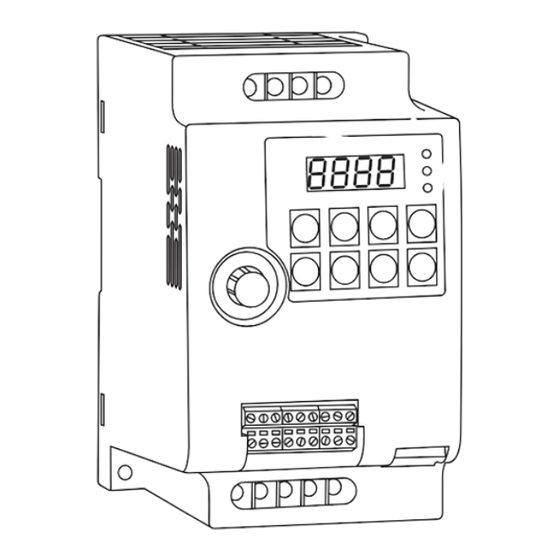
Page 17: Chapter 5 Operation Panel
Chapter 5 Operation Panel 5.1 Appearance Diagram SHIFT PROG << STOP M-FUN ENTER REST 5.2 Description of Indicators ◇ RUN: ON indicates that the AC drive is in the running state, and OFF indicates that the AC drive is in the stop state. ◇... -
Page 18: Key Instruction
5.3 Description of Keys on the Operation Panel Name Function PROG Programming Enter or exit Level I menu. Function switch selection. It can be defined as a Multifunction M-FUN command source, or as a fast direction switch, Selection according to P7-01. ▲... -
Page 19: Chapter 6 Function Parameter Table
Chapter 6 Function Code Table 6.1 Brief introduction of function code If PP-00 is set to a non-zero number, parameter protection is enabled. You must enter the correct user password to enter the menu. To cancel the password protection function, enter with password and set FP-00 to 0. Group P and Group A are standard function parameters. - Page 20 6.1 Brief introduction of function code P0 Standard Function Parameters Function Parameter Setting Range Default Property Code Name 0: Digital setting (preset frequency P0-08, press UP/DOWN to modify, non-retentive at power failure) 1: Digital setting (preset frequency P0-08, press UP/DOWN to modify, retentive at power failure) Main frequency 2: AI1...
- Page 21 6.1 Brief introduction of function code P0 Standard Function Parameters Function Parameter Setting Range Default Property Code Name Unit's digit (Frequency source selection) 0: Main frequency source X 1: X and Y operation (operation relationship determined by ten's digit) 2: Switchover between X and Y Frequency 3: Switchover between X and "X and Y source...
- Page 22 6.1 Brief introduction of function code P0 Standard Function Parameters Function Parameter Setting Range Default Property Code Name Frequency upper limit 0.00Hz ~ maximum P0-13 0.00Hz ☆ offset frequency P0-10 0.00Hz ~ frequency P0-14 Frequency lower limit 0.00Hz ☆ upper limit P0-12 Model P0-15 Carrier frequency...
- Page 23 6.1 Brief introduction of function code P0 Standard Function Parameters Function Parameter Setting Range Default Property Code Name 0: Maximum frequency (P0- Acceleration/ P0-25 Deceleration time ★ 1: Set frequency base frequency 2: 100 Hz Base frequency for UP/ 0: Running frequency P0-26 DOWN modification ★...
- Page 24 6.1 Brief introduction of function code P1 Motor Parameters Function Parameter Setting Range Default Property Code Name 0: Common asynchronous motor Motor type P1-00 2: Permanent magnetic ★ selection synchronous motor Model Rated motor P1-01 0.1kW ~ 1000.0kW ★ power dependent Rated motor Model...
- Page 25 6.1 Brief introduction of function code P2 Vector Control Parameters Function Parameter Setting Range Default Property Code Name Speed loop proportional P2-00 1 ~ 100 ☆ gain 1 P2-01 Speed loop integral time 1 0.01s ~ 10.00s 0.50s ☆ P2-02 Switchover frequency 1 0.00 ~...
- Page 26 6.1 Brief introduction of function code P2 Vector Control Parameters Function Parameter Setting Range Default Property Code Name Digital setting of torque P2-10 upper limit in speed 0.0% ~ 200.0% 150.0% ☆ control mode Excitation adjustment P2-13 0 ~ 60000 2000 ☆...
- Page 27 6.1 Brief introduction of function code P3 V/F Control Parameters Function Parameter Setting Range Default Property Code Name 0: Linear V/F 1: Multi-point V/F 2: Square V/F 3: 1.2 power V/F 4: 1.4 power V/F P3-00 VF curve setting 6: 1.6 power V/F ★...
- Page 28 6.1 Brief introduction of function code P4 Input Terminals Function Parameter Setting Range Default Property Code Name 0: No function 1: Forward RUN (FWD) or RUN DI1 terminal 2: Reverse RUN (REV) or RUN direction P4-00 function ★ 3: Three-line control selection 4: Forward JOG (FJOG) 5: Reverse JOG (RJOG)
- Page 29 6.1 Brief introduction of function code P4 Input Terminals Function Parameter Setting Range Default Property Code Name 27: Length count input 28: Length reset 29: Torque control prohibited 30: Pulse input (enabled only for DI5) 31: Reserved 32: Immediate DC braking 33: Normally closed (NC) input of external fault 34: Frequency modification enable...
- Page 30 6.1 Brief introduction of function code P4 Input Terminals Function Parameter Setting Range Default Property Code Name 0: Two-line mode 1 P4-11 Terminal command mode 1: Two-line mode 2 ★ 2: Three-line mode 1 P4-12 Terminal UP/DOWN rate 0.001Hz/s ~ 65.535Hz/s 1.00Hz/s ☆...
- Page 31 6.1 Brief introduction of function code P4 Input Terminals Function Parameter Setting Range Default Property Code Name Corresponding setting of P4-26 -100.0% ~ +100.0% 100.0% ☆ AI curve 3 maximum input Panel P4-27 potentiometer 0.00s ~ 10.00s 0.10s ☆ filter time HDI Pulse P4-28 0.00kHz ~...
- Page 32 6.1 Brief introduction of function code P4 Input Terminals Function Parameter Setting Range Default Property Code Name Unit's digit (Setting for AI1 less than minimum input) 0: Minimum value 1: 0.0% Setting for AI less Ten's digit (Setting for AI2 less P4-34 than minimum ☆...
- Page 33 6.1 Brief introduction of function code P5 Output Terminals Function Parameter Setting Range Default Property Code Name FM terminal 0: Pulse output (FMP) P5-00 ☆ output mode 1: Switch signal output (FMR) 0: No output 1: AC drive running 2: Fault output (stop) 3: Frequency-level detection FDT1 output 4: Frequency reached...
- Page 34 6.1 Brief introduction of function code P5 Output Terminals Function Parameter Setting Range Default Property Code Name 21: Reserved 22: Reserved 23: Zero-speed running 2 (having output at stop) 24: Accumulative power-on time reached 25: Frequency level detection FDT2 output 26: Frequency 1 reached output 27: Frequency 2 reached output 28: Current 1 reached output...
- Page 35 6.1 Brief introduction of function code P5 Output Terminals Function Parameter Setting Range Default Property Code Name 0: Running frequency 1: Set frequency 2: Output current 3: Output torque (absolute value) FMP output P5-06 ☆ 4: Output power function selection 5: Output voltage 6: HDI input (100.0% corresponds 100.0kHz)
- Page 36 6.1 Brief introduction of function code P6 Start/Stop Control Function Parameter Setting Range Default Property Code Name 0: Direct start 1: Rotational speed tracking restart P6-00 Start mode ☆ 2: Pre-excited start (asynchronous motor) Rotational 0: From frequency at stop P6-01 speed tracking 1: From power frequency...
- Page 37 6.1 Brief introduction of function code P6 Start/Stop Control Function Parameter Setting Range Default Property Code Name 0: Linear acceleration/ deceleration Acceleration/Deceleration P6-07 ★ mode 1: Static S-curve 2: Dynamic S-curve Time proportion of S-curve P6-08 0.0% ~ (100%-P6-09) 30.0% ★...
- Page 38 6.1 Brief introduction of function code P7 Operation Panel and Display Function Parameter Setting Range Default Property Code Name 0: MF.K key disabled 1: Switchover between operation panel control and remote command control (terminal or MF.K Key function P7-01 communication) ★...
- Page 39 6.1 Brief introduction of function code P7 Operation Panel and Display Function Parameter Setting Range Default Property Code Name 0000–FFFF Bit00: PID feedback Bit01: PLC stage Bit02: HDI setting frequency (kHz) Bit03: Running frequency 2 (Hz) Bit04: Remaining running time Bit05: AI1 voltage before correction (V) LED display Bit06: AI2...
- Page 40 6.1 Brief introduction of function code P7 Operation Panel and Display Function Parameter Setting Range Default Property Code Name Load speed display P7-06 0.0001 ~ 6.5000 1.0000 ☆ coefficient Heatsink temperature of P7-07 0℃~ 120℃ ● AC drive IGBT Accumulative running P7-09 0h ~...
- Page 41 6.1 Brief introduction of function code P8 Auxiliary Functions Function Parameter Setting Range Default Property Code Name 0.00Hz ~ maximum P8-00 JOG running frequency 2.00Hz ☆ frequency P8-01 JOG acceleration time 0.0s ~ 6500.0s 20.0s ☆ P8-02 JOG deceleration time 0.0s ~...
- Page 42 6.1 Brief introduction of function code P8 Auxiliary Functions Function Parameter Setting Range Default Property Code Name 0: Run at frequency Running mode when set lower limit P8-14 frequency lower than ☆ 1: Stop frequency lower limit 2: Run at zero speed P8-15 Droop control 0.00Hz ~...
- Page 43 6.1 Brief introduction of function code P8 Auxiliary Functions Function Parameter Setting Range Default Property Code Name Frequency detection value 0.00Hz ~ maximum P8-28 50.00Hz ☆ (FDT2) frequency Frequency detection 0.0% ~ 100.0% (FDT2 P8-29 5.0% ☆ hysteresis (FDT hysteresis 2) electrical level) Any frequency reaching 0.00Hz ~...
- Page 44 6.1 Brief introduction of function code P8 Auxiliary Functions Function Parameter Setting Range Default Property Code Name Any current reaching 0.0% ~ 300.0% (rated motor P8-41 0.0% ☆ 2 amplitude current) P8-42 Timing function 0: Disabled 1: Enabled ☆ 0: P8-44 1: AI1 2: AI2 Timing duration...
- Page 45 6.1 Brief introduction of function code P9 Fault and Protection Function Parameter Setting Range Default Property Code Name Motor overload protection 0: Disabled P9-00 ● selection 1: Enabled P9-01 Motor overload protection gain 0.20 ~ 10.00 1.00 ● Motor overload warning P9-02 50% ~...
- Page 46 6.1 Brief introduction of function code P9 Fault and Protection Function Parameter Setting Range Default Property Code Name 0: No fault 1: Reserved 2: Overcurrent during acceleration 3: Overcurrent during deceleration 4: Overcurrent at constant speed fault P9-14 ● 5: Overvoltage during acceleration type 6: Overvoltage during deceleration 7: Overvoltage at constant speed...
- Page 47 6.1 Brief introduction of function code P9 Fault and Protection Function Parameter Setting Default Property Code Name Range P9-17 Frequency upon 3 fault ● P9-18 Current upon 3 fault ● P9-19 Bus voltage upon 3 fault ● P9-20 Input terminal status upon 3 fault -...
- Page 48 6.1 Brief introduction of function code P9 Fault and Protection Function Parameter Setting Range Default Property Code Name Bus voltage upon P9-39 - ● fault Input terminal P9-40 - ● status upon 1 fault Output terminal P9-41 - ● status upon 1 fault AC drive status P9-42...
- Page 49 6.1 Brief introduction of function code P9 Fault and Protection Function Parameter Setting Range Default Property Code Name 0: Current running frequency Frequency selection for 1: Set frequency P9-54 continuing to run upon 2: Frequency upper limit 00000 ☆ fault 3: Frequency lower limit 4: Backup frequency upon abnormality...
- Page 50 6.1 Brief introduction of function code PA PID Function Function Parameter Setting Range Default Property Code Name 0: PA-01 1: AI1 2: AI2 PA-00 PID setting source 3: Panel potentiometer ☆ 4: HDI Pulse setting (DI5) 5: Communication setting 6: Multi-reference PA-01 PID digital setting 0.0% ~...
- Page 51 6.1 Brief introduction of function code PA PID Function Function Parameter Setting Range Default Property Code Name Cut-off frequency of PID 0.00 ~ maximum PA-08 2.00Hz ☆ reverse rotation frequency PA-09 PID deviation limit 0.0% ~ 100.0% 0.0% ☆ PA-10 PID differential limit 0.00% ~...
- Page 52 6.1 Brief introduction of function code PA PID Function Function Parameter Setting Range Default Property Code Name PA-21 PID initial value 0.0% ~ 100.0% 0.0% ☆ PID initial value PA-22 0.00 ~ 650.00s 0.00s ☆ holding time Maximum deviation between PA-23 0.00% ~...
- Page 53 6.1 Brief introduction of function code PB Swing Frequency, Fixed Length and Count Function Parameter Setting Range Default Property Code Name 0: Relative to the central Swing frequency setting frequency PB-00 ☆ mode 1: Relative to the maximum frequency Swing frequency PB-01 0.0% ~...
- Page 54 6.1 Brief introduction of function code PC Multi-Reference and Simple PLC Function Function Parameter Setting Range Default Property Code Name PC-00 Reference 0 -100.0% ~ 100.0% 0.0% ☆ PC-01 Reference 1 -100.0% ~ 100.0% 0.0% ☆ PC-02 Reference 2 -100.0% ~ 100.0% 0.0% ☆...
- Page 55 6.1 Brief introduction of function code PC Multi-Reference and Simple PLC Function Function Parameter Setting Range Default Property Code Name Unit's digit (Retentive upon power failure) 0: No 1: Yes ☆ PC-17 Simple PLC retentive selection Ten's digit (Retentive upon stop) 0: No 1: Yes Running time of simple PLC...
- Page 56 6.1 Brief introduction of function code PC Multi-Reference and Simple PLC Function Function Parameter Setting Range Default Property Code Name Running time of simple PLC PC-28 0.0s(h) ~ 6553.5s(h) 0.0s(h) ☆ reference 5 Acceleration/deceleration time PC-29 0 ~ 3 ☆ of simple PLC reference 5 Running time of simple PLC PC-30...
- Page 57 6.1 Brief introduction of function code PC Multi-Reference and Simple PLC Function Function Parameter Setting Range Default Property Code Name Running time of simple PLC PC-42 0.0s(h) ~ 6553.5s(h) 0.0s(h) ☆ reference 12 Acceleration/deceleration time PC-43 0 ~ 3 ☆ of simple PLC reference 12 Running time of simple PLC PC-44...
- Page 58 6.1 Brief introduction of function code PD Communication Parameters Function Parameter Setting Range Default Property Code Name Unit's digit: MODBUS 0: 300BPS 1: 600BPS 2: 1200BPS 3: 2400BPS 4: 4800BPS 5: 9600BPS 6: 19200BPS 7: 38400BPS 8: 57600BPS 9: 115200BPS Ten's digit: PROFIBUS-DP PD-00 Baud rate...
- Page 59 6.1 Brief introduction of function code PD Communication Parameters Function Parameter Setting Range Default Property Code Name 0: No check, data format <8,N,2> 1: Even parity check, data format <8,E,1> MODBUS data PD-01 2: Odd Parity check, data format ☆ format <8,O,1>...
- Page 60 6.1 Brief introduction of function code PP Function Code Management Function Parameter Setting Range Default Property Code Name PP-00 User password 0 ~ 65535 ☆ 0: No operation Restore default 01: Restore factory settings PP-01 ★ settings except motor parameters 02: Clear records Unit's digit (Group U display selection)
- Page 61 6.1 Brief introduction of function code A0 Torque Control Parameters Function Parameter Setting Range Default Property Code Name Speed/Torque control 0: Speed control A0-00 ★ selection 1: Torque control 0: Digital setting (A0-03) 1: AI1 2: AI2 3: Panel potentiometer 4: HDI pulse setting (DI5) Torque setting source in A0-01...
- Page 62 6.1 Brief introduction of function code A5 Control Optimization Parameters Function Parameter Setting Range Default Property Code Name DPWM switchover 5.00Hz ~ maximum A5-00 8.00Hz ☆ frequency upper limit frequency 0: Asynchronous modulation A5-01 PWM modulation mode ☆ 1: Synchronous modulation Dead zone 0: No compensation...
- Page 63 6.1 Brief introduction of function code U0 Monitoring Parameters Function Parameter Setting Default Property Code Name Range U0-00 Running frequency (Hz) 0.01Hz ● U0-01 Set frequency (Hz) 0.01Hz ● U0-02 Bus voltage (V) 0.1V ● U0-03 Output voltage (V) ● U0-04 Output current (A) 0.01A...
- Page 64 6.1 Brief introduction of function code U0 Monitoring Parameters Function Parameter Setting Default Property Code Name Range U0-24 Linear speed 1m/Min ● U0-25 Accumulative power-on time 1Min ● U0-26 Accumulative running time 0.1Min ● U0-27 HDI pulse input frequency ● U0-28 Communication setting value 0.01%...
-
Page 65: Chapter 7 Maintenance And Troubleshooting
Chapter 7 Maintenance and Troubleshooting 7.1 Fault Description If fault happens during the operation of the 780 inverter system, the inverter will stop the output immediately, and the inverter fault relay will make contact action. The inverter panel displays the fault code, the corresponding fault types and common solutions are shown in the table below. - Page 66 7.2 Troubleshooting List Fault Name Display Possible Causes Solutions 1: The output circuit is grounded 1: Eliminate external faults. or short circuited. 2: Perform the motor 2: Motor auto-tuning is not autotuning. performed. 3: Increase the 3: The acceleration time is too acceleration time.
- Page 67 7.2 Troubleshooting List Fault Name Display Possible Causes Solutions 1: Adjust the voltage to 1: The input voltage is too high. normal range. 2: An external force drives the 2: Cancel the external force Overvoltage motor during acceleration. or install a braking resistor. during Err05 3: The acceleration time is too...
- Page 68 7.2 Troubleshooting List Fault Display Possible Causes Solutions Name 1: Reduce the load and 1: The load is too heavy or check the motor and AC drive lockedrotor occurs on the motor. Err10 mechanical condition. overload 2: The AC drive model is of too 2: Select an AC drive of small power class.
- Page 69 7.2 Troubleshooting List Fault Name Display Possible Causes Solutions 1: The host computer is in 1: Check the cabling of host abnormal state. computer. 2: The communication Communication 2: Check the communication Err16 cable is faulty. cabling. fault 3: The communication 3: Set the communication parameters in group FD parameters properly.
- Page 70 7.2 Troubleshooting List Fault Name Display Possible Causes Solutions 1: The user-defined fault 2 User-defined signal is input via DI. Err28 Reset the operation. fault 2 2: The user-defined fault 2 signal is input via virtual I/O. Accumulative The accumulative power- Clear the record through power-on Err29...
-
Page 71: Faults And Solutions
7.3 Troubleshooting 1: There is no power supply to the AC drive or the power input to the AC drive 1: Check the is too low. power supply. 2: The power supply of the switch on the 2: Check the bus drive board of the AC drive is faulty. - Page 72 7.3 Troubleshooting 1: The setting of carrier frequency is too 1: Reduce the carrier Err14 (IGBT high. frequency (P0-15). overheat) 2: The cooling fan is damaged, or the air 2: Replace the fan and fault is filter is blocked. clean the air filter. reported 3: Components inside the AC drive are 3: Contact technical...
Need help?
Do you have a question about the V780 and is the answer not in the manual?
Questions and answers