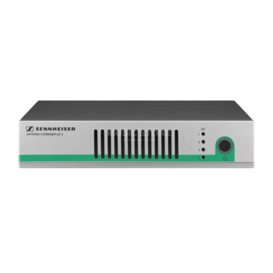
Summary of Contents for Sennheiser AC 3 - ANNEXE 748
- Page 1 Active Antenna Combiner AC 3 Bedienungsanleitung Instruction manual Istruzioni per l’uso Notice d’emploi Manual de instrucciones Manual de instruções инструкция по эксплуатации 本使用说明书...
-
Page 2: Table Of Contents
Thank you for choosing Sennheiser! We have designed this product to give you reliable operation over many years. Over 60 years of accumulated expertise in the design and manufacture of high-quality electro-acoustic equip- ment have made Sennheiser a world-leading company in this field. -
Page 3: Important Safety Instructions
• WARNING: To reduce the risk of fire or electric shock, do not use the device near water and do not expose it to rain or mois- ture. Do not place objects filled with liquids, such as vases or coffee cups, on the device. - Page 4 • using the device within the operating conditions and limita- tions described in this instruction manual. “Improper use” means using the AC 3 other than as described in this instruction manual, or under operating conditions which differ from those described herein.
-
Page 5: The Ac 3 Active Transmitter Combiner
The AC 3 active transmitter combiner With the AC 3 4-to-1 active transmitter combiner, the signals of up to four SR 300 IEM G3 type transmitters can be combined onto a single antenna. The integral active RF amplifiers ensure that the input signals are combined onto the common antenna output with no distri- bution attenuation. -
Page 6: Operating Controls
DC IN STANDBY button Operation indicator 4 status LEDs – light up if the supply voltage for the transmitter is avail- able at the BNC sockets RF IN 1 RF IN 4 – go off if the BNC sockets RF IN 1... -
Page 7: Block Diagram
Block diagram Block diagram The below block diagram shows the connections for a 4-channel system with a single antenna. NT 3-1 RF Output STANDBY AC 3 DC feed RF Inputs SR 300 SR 300 SR 300 SR 300... -
Page 8: Putting The Ac 3 Into Operation
The stacking elements (see “Accessories” on page 15) stacking elements are designed to help protect the operating elements from damage or deformation, e.g. if the AC 3 is dropped. Fasten the stacking elements even if you do not want to stack your AC 3. - Page 9 Clean the base of the AC 3 where you want to fix the device feet. Fix the device feet to the base of the AC 3 by peeling off the backing paper and fitting them as shown on the left.
- Page 10 Secure the rack mount “ears” (supplied with the optional one AC 3 GA 3 rack adapter) to the AC 3 in the same way as described for the stacking elements (see page 7). Secure the blanking plate to one of the rack mount “ears”...
- Page 11 Secure the rack mount “ear” and the blanking plate the 19” rack. Rack mounting To rack mount the AC 3 and an SR 300 IEM G3 type transmitter two devices into into the same 19” slot: the same 19” slot...
- Page 12 Putting the AC 3 into operation Secure the rack mount “ears” (supplied with the optional GA 3 rack adapter) to the devices as described in the section “Fastening the stacking elements” on page 7. Slide the devices into the 19” rack.
-
Page 13: Using The Ac 3
Switching the AC 3 on CAUTION! Risk of fire due to overheating of the AC 3! The AC 3 equipped with a fan to assist dissipation of generated heat. Make sure that the air vents of the AC 3 are not covered or blocked. -
Page 14: Cleaning The Ac 3
4 status LEDs go off. The AC 3 switches to standby mode. Connected transmitters » are switched off, provided that they are powered via the BNC sockets RF IN 1 RF IN 4 Disconnecting the AC 3 from the mains... -
Page 15: If A Problem Occurs
G2 series If a problem occurs that is not listed in the above table or if the problem cannot be solved with the proposed solutions, please contact your local Sennheiser partner for assistance. -
Page 16: Accessories
Accessories Accessories The following AC 3 accessories are available from your Sennheiser partner: Cat. No. Accessory/spare part 503159 NT 3-1 EU Table top power supply for powering the AC 3 and four transmitters, EU version 503876 NT 3-1 US Table top power supply for powering the AC 3... -
Page 17: Specifications
Relative humidity 5 to 95% Operating temperature range –10°C to +55°C Storage temperature range –20°C to +70°C Dimensions of housing approx. 212 x 168 x 43 mm Weight approx. 1470 g Type approvals In complicance with EN 301489-1/-9 Radio EN 300422-1/-2... -
Page 18: Manufacturer Declarations
In compliance with the following requirements • RoHS Directive (2002/95/EU) • WEEE Directive (2002/96/EU) Please dispose of the AC 3 at the end of its operational lifetime by taking it to your local collection point or recy- cling center for such equipment. - Page 19 Sennheiser electronic GmbH & Co. KG Printed in Germany Am Labor 1, 30900 Wedemark, Germany Publ. 03/09 www.sennheiser.com 532863/A01...


Need help?
Do you have a question about the AC 3 - ANNEXE 748 and is the answer not in the manual?
Questions and answers