Bose S1 PRO+ Service Manual
Wireless pa system
Hide thumbs
Also See for S1 PRO+:
- Manual (78 pages) ,
- Quick start manual (2 pages) ,
- Troubleshooting tips (2 pages)

Related Manuals for Bose S1 PRO+


Summary of Contents for Bose S1 PRO+
- Page 1 S1 PRO+ WIRELESS PA SYSTEM Service Manual ©2023 Bose Corporation Reference Number 869583-SM REV 04...
-
Page 2: Table Of Contents
CONTENTS Title Page SAFETY INFORMATION ...........................4 ELECTROSTATIC DISCHARGE SENSITIVE (ESDS) DEVICE HANDLING ..........5 WARRANTY..............................5 PART LIST NOTES ............................5 PRODUCT DESCRIPTION........................6-7 PACKAGING PART LIST ...........................8 Figure 1. Packaging Exploded View ......................8 MAIN ASSEMBLY LIST..........................9 Figure 2-4. Main Assembly Exploded View ..................10-12 Figure 5-6 IO Panel Assembly Exploded View...................13-14 MAIN-I/O PCB PART LIST........................15-22 POWER PCB PART LIST........................23-28... - Page 3 CONTENTS Title Page TRANSMITTER CHARGING AND TEST ....................45 CHECK FIRMWARE VERSIONS ON OLEDS....................46 HI-POT TEST...............................47 SOFTWARE UPDATE..........................48-49 SERVICE MANUAL REVISION HISTORY....................50...
-
Page 4: Safety Information
If it is not within the limits specified, there is the possibility of a shock hazard, and the unit must be repaired and rechecked before it is returned to the customer. CAUTION: The Bose S1 Pro+ Wireless PA System contains no user-serviceable parts. To prevent war- ranty infractions, refer servicing to warranty service stations or factory service. -
Page 5: Electrostatic Discharge Sensitive (Esds) Device Handling
WARRANTY The Bose S1 Pro+ Wireless PA System is covered by a limited 1-year transferable warranty. 2 years in Europe. PART LIST NOTES 1. The individual parts located on the PCBs are listed in the Electrical Part List. -
Page 6: Product Description
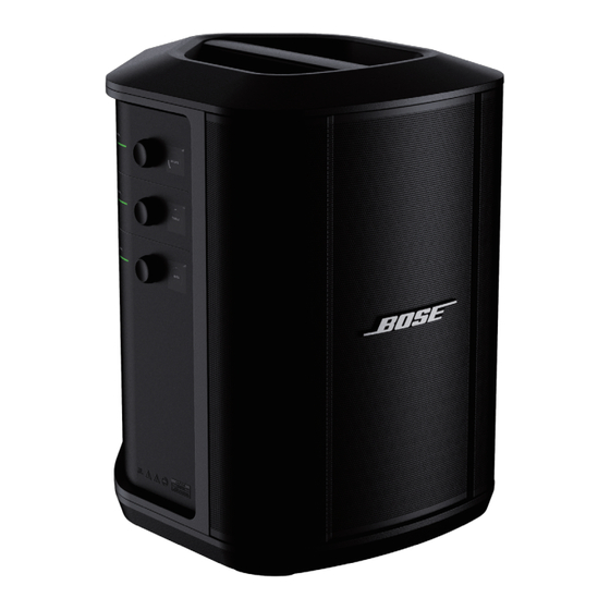
S1 Pro+ Wireless PA System is the next generation of the S1 Pro loudspeaker. Size and weight are sim- ilar to the S1 Pro. It uses the same input panel/controls form factor as the L1 Pro products and it is also compatible with Bose Music app. S1 Pro+ has full ToneMatch and Bluetooth capability. - Page 7 PRODUCT DESCRIPTION Wireless transmitter charging ports. Channel inputs (balanced/unbalanced combined or 6.35 mm TS/TRS and XLR). Signal/clip lights. Channel controls. Channel displays. TRS balanced mono line input ( or 6.35 mm TS/TRS). AUX stereo line input ( or 3.5 mm TRS). Bluetooth button.
-
Page 8: Packaging Part List
Packaging Part List Item Bose Part Description Note Quantity Number Number CARTON 867645-0010 PACKAGING,FOAM,EPE,FRONT 870576-0010 PACKAGING,FOAM,EPE,REAR 870577-0010 CARTON,LINE CORD 870579-0010 CABLE, LINE CORD, IEC C13, NA 350745-0010 CABLE, LINE CORD, IEC C13, EU 350747-0010 CABLE, LINE CORD, IEC C13, UK... -
Page 9: Main Assembly List
Main Assembly Part List (see Figure 2) S1 PRO+ Item Description Bose Material Quantity Note Number Number TWIDDLER, 2.5IN, NEO, TXX, SVCE 742631-002S WOOFER, 6IN, TYMPHANY 789361-001S ASSY, PCB, ANTENNA AND CABLE 796036-001S GRILLE SUBASSEMBLY, SVCE 866407-001S BATTERY, LG, SERVICE... - Page 10 Main Assembly Exploded View Figure 2. Main Assembly Exploded View S1 PRO+...
- Page 11 Main Assembly Exploded View Figure 3. Main Assembly Exploded View S1 PRO+...
- Page 12 Main Assembly Exploded View Figure 4. Main Assembly Exploded View S1 PRO+...
- Page 13 IO Panel Assy Exploded View Figure 5. IO Panel Assy Exploded View S1 PRO+...
- Page 14 IO Panel Assy Exploded View Figure 6. IO Panel Assy Exploded View S1 PRO+...
-
Page 15: Main-I/O Pcb Part List
MAIN-I/O PCB PARTS LIST Resistors Reference Designator Description Material Number Note R1, R325A, R325B, R336A, RES, THICK FILM, 0402, 0.063W, 1%, 2K 801703-2001F R336B R10-R11, R16-R17, RES, THICK FILM, 0402, 0.063W, 1%, 33 OHM 801703-33R0F R24-R26, R58, R64, R66, R68, R73-R74, R77-R79, R81, R84-R89, R91-R92, R99-R100, R102-R111, R120, R123,... - Page 16 MAIN-I/O PCB PARTS LIST Resistors (continued) Reference Designator Description Material Number Note R274, R281, R297, R308 RES, THICK FILM, 0805, 0.125W, 1%, 100 802354-1000F R275, R289, R294, R309 RES, THICK FILM, 0603, 0.1W, 1%, 14K 801706-1402F R276, R279, R439, R456 RES, THICK FILM, 0402, 0.063W, 1%, 20K 801703-2002F R277, R283, R295, R302...
- Page 17 MAIN-I/O PCB PARTS LIST Resistors (continued) Reference Designator Description Material Number Note R4, R6, R9, R19, R23, RES, THICK FILM, 0402, 0.063W, 1%, 120 801703-1200F R83, R96-R97, R156-R157, R160, R475-R477, R479-R481 R402 RES, THICK FILM, 0603, 0.1W, 1%, 56K 801706-5602F R403 RES, THICK FILM, 0603,0.1W, 1%, 3K 801706-3001F...
- Page 18 MAIN-I/O PCB PARTS LIST Capacitors Reference Designator Description Material Number Note C1, C112-C113, CAP, X5R, 0805, 50V, 10%, 4.7uF, COMM 743447-475K1H C124-C125, C252-C253, C257 C10, C133 CAP, C0G, 0402, 50V, 5%, 680pF, COMM 766718-681J1H C107, C218A, C218B CAP, C0G, 0402, 50V, 5%, 15pF, COMM 766718-150J1H C11, C17, C19, C84, CAP, X5R, 0402, 10V, 10%, 1uF, COMM...
- Page 19 MAIN-I/O PCB PARTS LIST Capacitors (continued) Reference Designator Description Material Number Note C23, C30, C32, C39, C76, CAP, X5R, 0402, 10V, 20%, 10uF, COMM 716994-106M1A C82, C88, C90, C92, C95, C103, C105, C140, C143, C148, C151, C154, C157, C242, C356-C357, C359-C360, C362, C365, C368, C379 C248, C255...
- Page 20 MAIN-I/O PCB PARTS LIST Diodes Reference Designator Description Material Number Note DIODE, SCHOTTKY, 2A, 60V, SOD123F 852398-0010 D14, D17-D18, D21, D27A, DIODE, SW, 75V, 0.3A, SOT-23, BAV99 747976-0010 D27B, D49A, D49B D22-D23, D28A, D28B, DIODE, SWITCHING, 100V, 0.15A, SOD323F 856395-0010 D29A, D29B D3, D24, D39-D40, D44, DIODE, TVS, BIDIR, 5V, 13pF, SOD882...
- Page 21 MAIN-I/O PCB PARTS LIST Transistors Reference Designator Description Material Number Note Q1, Q26-Q27, Q32-Q33, TRANSISTOR, MFET, N-CH, 0.3A, 60V, SOT- 356154-0010 Q36-Q37 TRANSISTOR, MFET, N-CH, 0.23A, 60V, 852240-0010 SOT363 Q15-Q18, Q23A, Q23B, TRANSISTOR, DUAL, COMP, 40V, 0.6A, 850060-0100 Q24A, Q24B 200mW, SOT-363 Q2-Q5 TRANSISTOR, NPN, 20V, 0.3A, 2SD2704K,...
- Page 22 MAIN-I/O PCB PARTS LIST Integrated Circuit Reference Designator Description Material Number Note EDG1 MODULE, RF, BLUETOOTH, BABY YODA 833933-0020 PTC, RESETTABLE, 0.75A, 100ms 320968-0754 CONN, FPC, 0.5mm C, 22P, 1R, R, SMT, RA, 857203-0022 CONN, PHONE JACK, 6.35mm, 3P, R, TH 873494-0010 J12A, J12B CONN, IO, XLR, 10P, R, TH, ST...
-
Page 23: Power Pcb Part List
POWER PCB PARTS LIST Resistors Reference Designator Description Material Number Note R1, R6, R97 RES, THICK FILM, 0402, 0.063W, 1%, 47K 801703-4702F R100, R108, R120, R122 RES, THICK FILM, 0603, 0.1W, 1%, 22 OHM 801706-22R0F R102, R112 RES, THICK FILM, 0603, 0.1W, 1%, 1 OHM 801707-1R00F R103, R118 RES, THICK FILM, 0805, 0.125W, 1%, 4.75... - Page 24 POWER PCB PARTS LIST Resistors (continued) Reference Designator Description Material Number Note R44, R47-R48, R110 RES, THICK FILM, 0603, 0.1W, 1%, 100K 801706-1003F R49-R50, R52-R53 RES, THICK FILM, 1206, 0.25W, 1%, 825K 806729-8253F R5, R11, R16, R113, RES, THICK FILM, 0402, 0.063W, 1%, 100K 801703-1003F R127-R129, R172-R173 R51,R54...
- Page 25 POWER PCB PARTS LIST Capacitors Reference Designator Description Material Number Note C1, C3-C4, C7, C9, C12, CAP, X7R, 0402, 50V, 10%, 0.1uF, COMM 718866-104K1H C15, C18, C72-C73, C76-C77, C96, C118-C119, C122, C125-C128, C137-C138, C141-C143, C159-C164, C176 C102, C117, C124, C130, CAP, X5R, 0805, 50V, 10%, 4.7uF, COMM 743447-475K1H C132, C144-C146, C156,...
- Page 26 POWER PCB PARTS LIST Capacitors (continued) Reference Designator Description Material Number Note CAP, X7R, HI VOLT, 0805, 500V, 10%, 470pF, 852020-471K2H COMM C86-C87 CAP, X7R, HI V, 1206, 1000V, 10%, 4700pF, 852057-472K3A COMM C88-C90, C100, C113, CAP, X7R, 0603, 50V, 10%, 0.1uF, COMM 718875-104K1H C129, C177-C178 C93-C94...
- Page 27 POWER PCB PARTS LIST Inductors Reference Designator Description Material Number Note BEAD, FERRITE, PWR, 1206, 4.5A, 270 OHM, 875917-271 COMM INDUCTOR, POWER, SMT, 23A, 20%, 3.3uH 873657-3R3M L15-L16 INDUCTOR, CUSTOM, COMM MODE, VERT, 873591-0010 1A, 12mH L1-L2 BEAD, FERRITE, HI PWR, 1206, 12A, 50 OHM, 872475-500 COMM L3, L5, L14...
- Page 28 POWER PCB PARTS LIST Miscellaneous Reference Designator Description Material Number Note 871274-5R00A FUSE, TIME LAG, RADIAL, AMMO PACK, 250V, 5A F2-F3 FUSE, SLO-BLO, 1206, 63V, 1.5A 871804-1R50 CONN, HDR, 2mm C, 6P, 1R, P, TH, ST, WHT 859609-0006 CONN, FPC, 0.5mm C, 22P, 1R, R, SMT, RA, 857203-0022 CONN.HDR, 2.5mm PITCH, 6P, P, TH, ST, 871254-0163...
-
Page 29: Display Pcb Part List
DISPLAY PCB PARTS LIST Resistors Reference Designator Description Material Number Note R15, R59-R67, R70-R71, JUMPER, CHIP, 0402 806732-0402 R73-R76 R19-R21 RES, THICK FILM, 0402, 0.063W, 1%, 1.2M 801703-1204F R1-R2 JUMPER, CHIP, 0603 806732-0603 R24-R26 RES, THICK FILM, 0402, 0.063W, 1%, 100K 801703-1003F R37-R39, R48-R53 RES, THICK FILM, 0402, 0.063W, 1%, 10K... -
Page 30: Pole Switch Pcb Part List
POLE SWITCH PCB PARTS LIST Miscellaneous Reference Designator Description Material Number Note CONN, HDR, 1.5mm C, 2P, 1R, P, SMT, ST, 847746-0020 BEIGE SWITCH, SENSOR, 1mA, 12VDC, 4P, DIP 860329-0010... -
Page 31: Disassembly Procedure
DISASSEMBLY PROCEDURE CAUTION: The SMD integrated circuits used on the Main-I/O board are extremely sensitive to ESD damage. Be sure to use an approved and tested ESD strap that is properly grounded to your work bench before attempting disas- sembly or repair of the S1 Pro+ Wireless PA system. - Page 32 DISASSEMBLY PROCEDURE 1.5 Use your hands and lift up on the I/O panel assy. 1.6 Detach the AC cables. See Figure 11. Figure 11. Detach the AC cables 1.7 Once the I/O panel assy is out from the Cabinet you will notice that the 2 transmitter FFC cables &...
- Page 33 DISASSEMBLY PROCEDURE 2.3 Remove the 12 screws securing the Bottom Cover as indicated in Figure 14. Figure 14. 12 screws Location 2.4 Once the Bottom Cover is out from the Cabinet, you will notice that the cable con- nects to the power port and the cables &...
- Page 34 DISASSEMBLY PROCEDURE 4. Twiddler Removal 4.1 Perform procedure 3. 4.2 Remove the 4 screws that secure the Twiddler as indicated in Figure 17. Figure 17. 4 screws Location Note: When installing the Twids Cable, RTV needs to be used to prevent buzz and vibra- tion.
- Page 35 DISASSEMBLY PROCEDURE 6. Main-I/O Board Removal 6.1 Perform procedure 1. 6.2 Remove the 7 screws that secure the Main-I/O board as indicated in Figure 21. 6.3 Detach the 1 FFC cable that attaches to the Display board as red arrow indicated in Figure 21.
- Page 36 DISASSEMBLY PROCEDURE 7.6 Remove the Gasket. See Figure 25 (left). 7.7 Clean the Alcohol. See Figure 25 (right). Re-assembly Note: Place the new OLED and OLED Gasket to ensure proper adhesion during reassembly. OLED Part Number : 868546-0010 OLED Gasket PN: 868705-0010 Figure 25.
- Page 37 DISASSEMBLY PROCEDURE 10. 3 Antenna Removal 10.1 Perform procedure 3. 10.2 Remove the 11 screws that secure the Top Cover. See Figure 29. Figure 29. 11 screw Location 10.3 Remove the Cabinet. The Bluetooth An- tenna is on the Top Cover. See Figure 30. Figure 30.
-
Page 38: Replace The System Battery
REPLACE THE SYSTEM BATTERY 1. Press the Power button to power off the sys- 5. Replace the bottom plate, then tighten the two tem, then disconnect the system from power. screws until secure. 2. Turn the system upside down. Loosen the two screws, then remove the bottom plate. -
Page 39: Test Procedure
TEST PROCEDURE Required Equipment: 1. Bose S1 Pro+ Wireless PA System (unit under test) 2. Audio Signal Generator, Audio Precision ATS-1 or equivalent 3. iPod Touch/Smart Phone with audio test files / music installed 4. Multi-meter 5. Cables listed below:... - Page 40 TEST PROCEDURE 2. Line Input / Output Verification Tests 2.1 Connect the AC power cord to the power port and to AC Mains. Press the Power button (15) to turn on the unit. The button should illuminate solid white. 2.2 Set the channel 1 volume control (4) to 50%. 2.3 Input a balanced 150 mV, 1 kHz audio signal into the Channel 1 audio input (2).
- Page 41 While connected, stream music audio and verify that you have clean audio playback. 4.3 Download and install Bose Music app on the Smart phone or other device. It is available at the Apple App Store and Google Play. Open the app and verify that you can connect to the product and control it using the app.
- Page 42 TEST PROCEDURE 7. Button Extended Functions Test 7.1 Perform the button tests below to verify extended functionality of the buttons/control. Product I/O User Trigger User action control Short press the power button Power LED on and system power on/ when system is off/on off.
- Page 43 Note: cable (not provided) to the USB POWER a. You can restore your channel and system port on the system. settings after a system reset using the Bose Music app. 10.2 Connect the other end to your mobile device. b. The first step to troubleshooting should be to perform a full system reset to ensure a consistent starting point.
-
Page 44: System Battery Charging And Test
SYSTEM BATTERY CHARGING AND TEST 11. Charging the System Battery 13. System Battery Level Test 11.1 When the S1 Pro+ is plugged into AC 13.1 On the Channel 3 display, battery icons Mains, the Power light pulses white to indicate show the system battery level and charging that the system battery is charging. -
Page 45: Transmitter Charging And Test
TRANSMITTER CHARGING AND TEST Note: You can also check the transmitter 14. Charging a Wireless Transmitter battery level by powering the transmitter on. 14.1 Fully insert the wireless transmitter into the wireless transmitter charging port for either Channel 1 or 2. 14.2 If the system is powered on, on the channel display, a battery icon with a lightning bolt next to it briefly appears to indicate that the... -
Page 46: Check Firmware Versions On Oleds
CHECK FIRMWARE VERSIONS ON OLEDS S1 Pro+ system comprises of following items which are updatable. It is important to make sure that these components are updated properly. • CSR68015 Bluetooth SoC • STM32F401VE I/O MCU • SYNCOMM Wireless RX Modules Ch1/Ch2 •... -
Page 47: Hi-Pot Test
HI-POT TEST 1. Hi-Pot Test Procedure THIS IS A MANDATORY TEST 1.1 Connect the positive side (hot) of the Hi-Pot tester to both terminals of the AC mains CAUTION - All units that are disassembled as input. part of a repair MUST be Hi-Pot tested before being returned to the customer. -
Page 48: Software Update
Wireless PA System is not compatible with Thunderbolt 3 cables. Google Chrome, Mozilla Firefox On a computer, open a web browser and go to btu.bose.com. Note: Not compatible with Internet Explorer or Safari. Click Download to download the Bose Updater. - Page 49 SOFTWARE UPDATE If your product needs a software update, your screen will read, There’s an update available for your product! S1 Pro+ Wireless PA System Click Update Now. Note: S1 Pro+ Wireless PA System 10. Once the update is complete, your screen will read, Your product is now up-to-date!. S1 Pro+ Wireless PA System...
-
Page 50: Service Manual Revision History
SERVICE MANUAL REVISION HISTORY Revision Changes Driven Pages (s) Date Description of Changes Level Affected 6/9/2023 Document released at revision 00 Initial Release 11/2/2023 Update QSG part numbe 11/8/2023 Update Encoder Switch part number 11/30/2023 Add note for item 137 Add the new page for "Check FW 12/1/2023 versions on OLEDs". - Page 51 Bose Corporation 100 The Mountain Road Framingham Massachusetts USA 01701 Reference Number 869583-SM REV 04, 12/2023 http://serviceops.bose.com...
Need help?
Do you have a question about the S1 PRO+ and is the answer not in the manual?
Questions and answers