Advertisement
Quick Links
Advertisement

Related Manuals for UTAH SCIENTIFIC UCP-SD16


Summary of Contents for UTAH SCIENTIFIC UCP-SD16
- Page 1 UCP-SD16 Router Switch Control Panel Installation and Operations Guide...
-
Page 2: Ucp-Sd16 - Router Switch Control Panel
Printed in U.S.A. Copyrights and Trademarks © 2005 Utah Scientific, Inc., All rights reserved. Any use or reproduction of this guide’s contents without the prior written consent of Utah Scientific, Inc. is strictly prohibited. UCP-SD16 is a trademark of Utah Scientific, Inc. -
Page 3: Declaration Of Conformity
Following the provisions of the Directive(s) of the Council of the European Union: EMC Directive 89/336/EED • • Low Voltage Electrical Directive 72/23/EEC Utah Scientific, Inc. hereby declares that the product specified above conforms to the above Directive(s) and Standard(s). UCP-SD16 - Router Switch Control Panel... -
Page 4: Important Safeguards And Notices
• The AC receptacle (socket) should be located near the equipment and be easily accessible. Disconnect power before cleaning. Do not use any liquid or aerosol • cleaner - use only a damp cloth. UCP-SD16 - Installation and Operations Guide... -
Page 5: Cautions
When the adjacent symbol is indicated on the chassis, please refer to • the manual for additional information. For the HD-2020 Chassis and Master Control Panel, refer to “Connect- • ing and Disconnecting Power” - Chapter 2 (Hardware Installation). UCP-SD16 - Router Switch Control Panel... -
Page 6: Company Information
Technical Services (FAX): +1 (801) 537-3069 • E-Mail -General Information: info@utsci.com E-Mail -Technical Services: service@utsci.com • • World Wide Web: http://www.utahscientific.com After Hours Emergency: +1 (800) 447-7204. Follow the menu instructions for Emergency • Service. UCP-SD16 - Installation and Operations Guide... -
Page 7: Warranty Policies
Warranty Policies Hardware Warranty Utah Scientific, Inc. warrants to the original purchaser that the Utah Scientific hardware is free from defects in materials and workmanship and will perform substantially in accordance with the accompanying written materials under normal use and service for a period of (10) years from the date of shipment. - Page 8 No liability for consequential damages. To the maximum extent permitted by applicable law, in no event shall Utah Scientific or its suppliers be liable for any damages whatsoever (including without limitation, damages for loss of business profits, business interruption, loss of...
-
Page 9: Table Of Contents
Table of Contents Table of Contents UCP-SD16 - Router Switch Control Panel ....ii Copyrights and Trademarks ........ii Notice ............... ii FCC Compliance ............ii Declaration of Conformity ......... iii Important Safeguards and Notices ......iv Safety Symbols ............... iv Warnings ................. - Page 10 Supervisor Panel ..........3-18 Panel Security Buttons ............3-18 PROTECT ............3-19 LOCK ..............3-19 CLEAR .............. 3-19 Security Status ..............3-20 Attribute Take ............3-22 UCP-SD16 Panel changes to support attributes.....3-22 DST: .................3-23 ATTR: ................3-23 LVL: .................3-23 STAT: ................3-24 TOC-ii...
- Page 11 Table of Contents Here is an Example: .......... 3-24 Additional Panel Lock Detail ........3-25 How to use the panel lock feature: ......... 3-25 Specifications APPENDIX A Product Specification ..........A-2 TOC-iii UCP-SD16...
- Page 12 TOC-iv Contents...
-
Page 13: Introduction
Introduction CHAPTER 1 This chapter provides an overview of the UCP-SD16 control panel and con- tains the following: Product Description ..............1-2 Product Overview ..............1-3 Front Panel ................1-3 Back Panel ................1-4 Features and Capabilities ............1-5 UCP-SD16/Router Operation .......... -
Page 14: Product Description
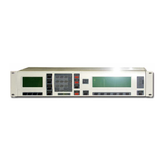
UCP-SD16 FIGURE 1-1. The UCP-SD16 makes use of graphic displays and softkeys along with a relatively flat menu to provide a powerful and easy to use router control panel. This 2 RU device operates using an external 12 VDC power supply and communicates with the router controller via U-NET communications. -
Page 15: Product Overview
Product Overview Product Overview Front Panel Shown below are the components that make up the front panel of a UCP-SD16. UCP-SD16 Front Panel View FIGURE 1-2. Table 1-1 provides information on the major panel components called out in Figure 1-2. -
Page 16: Back Panel
Introduction Back Panel Shown below are the components that make up the back panel of the UCP-SD16. UCP-SD16 Back Panel View FIGURE 1-3. Table 1-2 provides information on the components called out in Figure 1-3. Back Panel Components TABLE 1-2. -
Page 17: Features And Capabilities
• Source toggle functionality • Level LEDs illuminate to quickly determine levels selected • Ability to daisy-chain up to thirty two panels per controller UNET port • Plug-in modules can be swapped for left or right hand data entry UCP-SD16... - Page 18 Understanding the operation of the UCP requires a basic knowledge of router operation. The router that is controlled by a UCP-SD16 contains one or more matrix boards. For example, a matrix could contain 16 signal input ports referred to as sources and 16 signal output ports referred to as destinations.
- Page 19 You would execute a breakaway if you wanted the video from one source and the audio from a different source. Where to Go Next Chapter 2, “Installation”, provides information for the proper installation of the UCP-SD16 con- trol panel. UCP-SD16...
- Page 20 Introduction Introduction...
- Page 21 Installation CHAPTER 2 This chapter provides information on installing the UCP-SD16 and contains the following: Site and Tool Requirements ........... 2-2 Site Requirements ..............2-2 Required Hardware Tool ............2-2 Required Software Tool ............2-2 Shipment Contents and Unpacking ........2-2 Shipment Contents ..............
- Page 22 Installation Site and Tool Requirements Site Requirements The UCP-SD16 panel is a 2 RU device designed to be rack-mounted in a standard 19” wide equipment rack. Refer to Specifications page A-1, for details concerning the environmental specifications of this device.
- Page 23 FIGURE 2-1. 10’ U-NET Cable (P/N 94005-0010) • U-NET Cable FIGURE 2-2. • VDC Power Supply (AC input: P/N 94001-0101 / DC input: P/N 80319-1) 12 VDC Power Supply FIGURE 2-3. • UCP-SD16 Installation and Operation Guide (P/N 82101-0057) UCP-SD16...
-
Page 24: Unpacking
Caution The UCP-SD16 contains static-sensitive CMOS circuitry. Proper handling and grounding mea- sures are required during this procedure to control static discharges. Be sure you are properly grounded before removing modules from the chassis unit. - Page 25 1.Position module in front of chassis at desired location. Guide module into front of chassis, ensuring proper alignment and docking of 64 pin connector. 2.Install 3 screws that secure module to top of chassis. 3.Install 3 screws that secure module to bottom of chassis. 4.Repeat steps 1, 2, and 3 for remaining module. UCP-SD16...
-
Page 26: Installing The Unit
Installation Installing the Unit The UCP-SD16 is a 2 RU device designed to be rack-mounted in a standard 19” (48.26 cm) wide equipment cabinet. These devices can be installed as a single unit or they can be daisy- chained together via the U-NET connectors (1) and U-NET cable. - Page 27 Connect the U-NET cable between either one of the U-NET ports on the back panel of the UCP-SD16 (refer to Figure 2-5 on page 2-6, callout #1) and the U-NET port on the back of the controller. In a daisy-chain configuration of panels, attach the cable to the device positioned before the panel on the network.
-
Page 28: U-Net Cable
Installation U-NET Cable Each UCP-SD16 panel is supplied with a 10 foot U-NET cable used for communications between the controller and the panel. This is a standard 10Base-T cable—any off-the-shelf cable conforming to the IEEE 802.3 standard can be used for this application. -
Page 29: Where To Go Next
1 and 2. It is imperative that wires in each of the pairs remain in that pair in order to retain the balanced properties of the cable. Where to Go Next For panel operation information, proceed to Chapter 3, “Using the UCP SD16”. UCP-SD16... - Page 30 Installation 2-10 Installation...
-
Page 31: Using The Ucp-Sd16
Using the UCP-SD16 CHAPTER 3 This chapter covers the operation of the UCP-SD16 control panel and con- tains the following: Overview of Front Panel Modules .......... 3-2 Panel Operation ..............3-6 Direct Takes ................3-10 Data Entry and Panel Menu Screens ........3-11 Panel Security ................ -
Page 32: Overview Of Front Panel Modules
Using the UCP-SD16 Overview of Front Panel Modules Once the unit is configured and installed, all router control operations are performed using the two front panel modules: the status (1) and data entry (2) modules. This chapter describes in detail the components that make up each module. -
Page 33: Status Module
Overview of Front Panel Modules Status Module The primary function of this module is to display the status of the router matrix source-to-desti- nation configurations. Status Panel FIGURE 3-3. UCP-SD16... - Page 34 Using the UCP-SD16 Status Panel Callouts (refer to Figure 3-2) TABLE 3-1. Item Name Description Navigation Buttons Three buttons used for paging through information dis- played on Status Module LCD (1). Navigation Buttons • Press top button to page up.
-
Page 35: Data Entry Module
Overview of Front Panel Modules Data Entry Module The primary function of this module is to provide both set up and operational capabilities for the UCP-SD16. Data Entry Panel FIGURE 3-4. Data Entry Panel Callouts TABLE 3-2. Item Name Description... - Page 36 Using the UCP-SD16 Data Entry Panel Callouts TABLE 3-2. Item Name Description Security Buttons THREE BUTTONS associated with protecting a destination and its assigned source from acciden- tal changes: PROTECT - Depending on security level of other network panels, prevents other panels from mak- ing source selection changes to a destination.
-
Page 37: Panel Operation
Panel Operation Panel Operation The UCP-SD16 operates in a numeric style of source, destination, and level selection. With numeric style, all sources, destinations, and levels are referred to by unique numbers assigned to each. The keypad located on the data entry module is used to directly select and enter the destination and source numbers for each level of destination. -
Page 38: Selecting A Destination
Using the UCP-SD16 Selecting a Destination To select destination 167: Select <DEST> using corresponding softkey on data entry module. Data entry LCD indicates destination softkey has been selected (reverse print DEST). Destina- tion field displayed with dash line indicating new destination selection should be made. -
Page 39: Selecting Levels For Breakaway
Status module LCD displays current level map. Select required levels (L-1, L-2, L-3) for breakaway using corresponding level- selection keys on data entry module keypad. As levels are selected, dash line appears after level number indicating level is ready for source selection. UCP-SD16... -
Page 40: Selecting A Source
Using the UCP-SD16 Selecting a Source To select source 189: Select <SRC> using corresponding softkey on data entry module. LCD indicates source softkey has been selected (reverse print SRC). Source field displayed with dash line indicating new source selection should be made. -
Page 41: Protecting The Destination
167. Direct Takes A button-per-source style of operation can also be supported using the UCP-SD16’s status module. Each of the 6 softkeys located below the status module’s LCD can be programmed to function as a dedicated source selection button. -
Page 42: Data Entry And Panel Menu Screens
Using the UCP-SD16 Press a softkey on the status module (instead of pressing the TAKE button). The soft- key you press will be the one to which the source is assigned. Data Entry and Panel Menu Screens Main Menu Icons The table below illustrates the Main Menu Icons used in the SC16 panel. -
Page 43: Menu Tree
Data Entry and Panel Menu Screens Menu Tree The illustration below contains a simple menu tree designed to assist in UCP-SD16 menu navigation. Logo - Startup Screen Main Menu 1 Menu Main Menu 1 Take Breakaway Destination Tools Error Panel... - Page 44 Using the UCP-SD16 The Error/Warning and Output Monitor Displays FIGURE 3-6. This illustration contains the first (left) and second (right) scroll screens within the Options Dis- play. Options Displays FIGURE 3-7. 3-14 Using the UCP-SD16...
-
Page 45: Basic Rules
Data Entry and Panel Menu Screens Final Scroll Screen - Options Display FIGURE 3-8. The Info Display Screen FIGURE 3-9. Basic Rules The following basic rules are covered in this section: Arrows and Lists • Locks and Protects • 3-15 UCP-SD16... - Page 46 Using the UCP-SD16 Arrows and Lists Up and Down Arrows are used on the display to indicate specific information about lists. These arrows appear only in the Error and Tool menus on the SD16 Data Entry Panel. They are below the list display and bracketed above their respective control buttons.
- Page 47 With the Protect in effect, the route can only be changed by the panel which initiated the • protect. • Another user may unprotect the route by using another panel to: unprotect the protected route change the route as required. Note: Any available panel can be used to ‘unprotect’ a protected route. 3-17 UCP-SD16...
-
Page 48: Panel Security
A network of UCP-SD16’s can consist of a mix of operator and supervisor panels or it can con- tain panels that are all programmed with the same security level. The needs of the system would dictate how each panel is programmed. -
Page 49: Protect
To clear a protect or lock function: Select protected or locked destination from data entry module Press <CLEAR> button. Lock or Protect indicator is no longer illuminated—indicating destination is no longer locked or protected—and the padlock icon is removed. 3-19 UCP-SD16... -
Page 50: Security Status
Using the UCP-SD16 Security Status The security status for a currently selected destination and the panel can be determined by looking at the indicators (1) located above each of the Protect, Lock, and Clear security buttons. Security Buttons FIGURE 3-10. - Page 51 To clear or reset the security status requires use of the panel that initiated the protect or lock or a supervisor panel. Amber Destination is either protected or locked depending on the indicator that is lit. Panel can clear or reset security status. 3-21 UCP-SD16...
-
Page 52: Attribute Take
Using the UCP-SD16 Attribute Take UCP-SD16 Panel changes to support attributes. Press the MENU button to display the following menu. Press the MENU button again to display the second menu. Select the attribute option by selecting the button below the ATTR icon. -
Page 53: Dst
8 – Mute Right 9 – Mute All 0 – Normal A – DV143 B – DV177 C – DV270 D – DV360 LVL: Pressing the LVL button will allow you to select specific levels to assign the attribute to. 3-23 UCP-SD16... -
Page 54: Stat
Using the UCP-SD16 STAT: The STAT button is used to allow you to view the sources and destinations without going back to the AllFollow Take screen. Here is an Example: In this example we will switch MIX on all levels in Numeric Mode. -
Page 55: Additional Panel Lock Detail
From the main menu press the MENU button to get to the sub menu. This menu has the Options, Info, Attributes, and Panel Lock. Select the Panel Lock icon by pressing the button beneath the icon. The following screen appears. 3-25 UCP-SD16... - Page 56 Using the UCP-SD16 To lock the panel the user must enter the password that was configured in the options menu. After the user has typed in the password press the DONE button. If the password has been entered correctly the following screen will appear.
-
Page 57: Appendix A Specifications
Specifications APPENDIX A This section contains UCP-SD16 control panel specification information. UCP-SD16 Installation and Operations Guide... -
Page 58: Product Specification
Specifications Product Specification Listed below are the specifications for the UCP-SD16 control panel. UCP-SD16 Specifications TABLE A-1. Dimensions 3.75”H x 19” W x 6” D Weight <7.0 lbs. Ambient Temperature 10° - 40° Celsius Relative Humidity 0 - 90%, non-condensing... - Page 59 High Definition Video 1-6 Breakaway selecting levels 3-9 breakaway 1-7 Icons Main menu 3-12 IEEE 802.3 2-8 Chassis Indicators UCP-SD16 1-3 U-NET 1-4 Clear 3-6, 3-19 Info Display Screen 3-15 CMOS circuitry 2-4 Installation 2-1 Components module 2-5 back panel 1-4...
- Page 60 Router Operation 1-6 Weight A-2 SC-3 1-2 Screens Data Entry and Panel Menu 3-12 Security Buttons 3-6 Security Status 3-20 indicators 3-21 Shift Button 3-4 Shipment Contents 2-2 signal input ports 1-6 Site Requirements 2-2 UCP-SD16 - Installation and Operations Guide...
Need help?
Do you have a question about the UCP-SD16 and is the answer not in the manual?
Questions and answers