Table of Contents
Advertisement
Advertisement
Table of Contents

Related Manuals for UTAH SCIENTIFIC UCP LC Series


Summary of Contents for UTAH SCIENTIFIC UCP LC Series
- Page 1 UCP LC Series Basic Setup and Operation UCP 16, 32, and 80...
- Page 2 Information contained in this guide is subject to change without notice or obligation. While every effort has been made to ensure that the information is accurate as of the publication date, Utah Scientific, Inc. assumes no liability for errors or omissions. In addition, Utah Scientific, Inc. assumes no responsibility for damages resulting from the use of this guide.
- Page 3 Following the provisions of the Directive(s) of the Council of the European Union: • EMC Directive 89/336/EED • Low Voltage Electrical Directive 72/23/EEC Utah Scientific, Inc. hereby declares that the product specified above conforms to the above Directive(s) and Standard(s). UCP LC 32/80...
- Page 4 Important Safeguards and Notices This section provides important safety guidelines for the Operator and Service Personnel. Specific warnings and cautions are found throughout the guide where they apply, but may not appear here. Please read and follow the important safety information, specifically those instructions related to risk of fire, electric shock, or injury to persons.
- Page 5 • Dangerous voltages exist at several points in this product. To avoid personal injury, do not touch exposed conductors and components while power is on. Do not insert anything into either of the systems two-power supply cavities with power connected. •...
- Page 6 Company Information Utah Scientific, Incorporated 4750 Wiley Post Way, Suite 150 Salt Lake City, Utah 84116-2878 U.S.A. • Telephone: +1 (801) 575-8801 • FAX: +1 (801) 537-3098 • Technical Services (voice): +1 (800) 447-7204 • Technical Services (FAX): +1 (801) 537-3069 •...
- Page 7 Warranty Policies Hardware Warranty Utah Scientific, Inc. warrants to the original purchaser that the Utah Scientific hardware is free from defects in materials and workmanship and will perform substantially in accordance with the accompanying written materials under normal use and service for a period of ten (10) years from the date of shipment.
- Page 8 Utah Scientific products, even if Utah Scientific has been advised of the possibility of such damages. Because some states/jurisdictions do not allow the exclusion or limitation of liability for consequential or incidental damages, the above limitation may not apply in those circumstances.
-
Page 9: Table Of Contents
Section 1 Section 1 Section 1 Overview - LC Panel Operation ..............1-1 Contents ..................... 1-1 Basic Chassis Configuration ..............1-2 System Introduction ................. 1-5 Launching UCON ................1-5 Layout Selection - Examples ............1-9 7x2 and 1x2 ................. 1-11 18x2 .................... - Page 10 Table of Contents...
- Page 11 Section 1 Overview - LC Panel Operation This guide describes the basic layout and operation of the LC 32/80 panel within the UCON interface. Contents Basic Chassis Configuration ..............1-2 System Introduction ................. 1-5 Launching UCON ................1-5 Blank Panel Setup ................1-14 Panel Operation ..................
-
Page 12: Basic Chassis Configuration
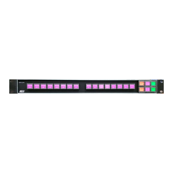
Basic Chassis Configuration Figure 1-1. LC16 Configuration UCP Series... - Page 13 Figure 1-2. LC32 Configuration UCP LC 32/80...
- Page 14 Figure 1-3. LC80 Configuration UCP Series...
-
Page 15: System Introduction
System Introduction Launching UCON Launch UCON by double-clicking the application icon inside the directory. FIGURE 1-1. Next, open the .ucn file saved for your current configuration. FIGURE 1-2. UCP LC 32/80... - Page 16 Once opened, your saved configuration will appear within the UCON display. Figure 1-4. Now double-click the layout configuration (noted icon above) to activate your working interface. You can also activate the panel editing window (shown below) by right-clicking the icon and selecting ‘Edit’ from the drop-down menu. FIGURE 1-3.
- Page 17 Previously created sources and destinations are listed alphabetically in the two lists at the right side of the display. The items contained in the functions list (lower-right) can be directly applied to individual buttons. FIGURE 1-4. The items that will be placed in the Name column are known as “Menus”, and in our example there are 32.
- Page 18 The layouts within the corresponding column are available for any one of the indicated ‘menus’ to the left (Name column). The Panel Layout selection is made by clicking the drop down menu within the layout column (illustration below) and making a selection from the list provided. Figure 1-5.
-
Page 19: Layout Selection - Examples
Layout Selection - Examples The illustration below contains a partition (1) 16x2 navigation panel. Sixteen buttons along the top by two rows. Figure 1-7. 16x2. In the following config there is no ‘Partition 2’, as partition 2 would contain the navigation buttons, which are not modifiable. - Page 20 The buttons to the far right are typically used as navigation buttons, and can include page up and page down controls. Important note concerning the ‘single mode' operation • It is always a good idea to include a ‘back’ button for the purpose of returning to a previous menu layout, otherwise the user is isolated in the current button layout.
-
Page 21: 7X2 And 1X2
Remember that page UP and page DOWN will cycle through sources and destinations. If you would like to step back to a previous layout however, use the ‘Back’ button, which is located in the same column as Page Up and Page Down. Figure 1-12. -
Page 22: 18X2
18x2 This corresponds to 18 inputs by two rows, all on the same partition. This layout allows all status visibility within the same partition. Figure 1-14. 18x2 Partition Display - 8x2 Configuration Figure 1-15. In this configuration the Sources are displayed within the tables by clicking the light green buttons on the virtual panel. - Page 23 The Destinations are shown in the tables by clicking the blue buttons on the virtual panel. The 3rd partition (red navigation buttons) are not modifiable. Figure 1-16. Destinations The right (blue) buttons are populated with sources by making a list selection from the column shown and dragging all items to the middle table.
-
Page 24: Blank Panel Setup
Blank Panel Setup During an initial blank panel setup, all menus are defined from scratch within the left-most column, labeled 'menu'. Figure 1-17. Blank panel Figure 1-18. Menu column 1-14 UCP Series... -
Page 25: Functions
Functions The Function selection is located within the listing at the lower-right corner of the screen display. These individual functions are used to populate the actual function table (center of the screen) for each one of the panels created. Figure 1-19. Functions selection 1-15 UCP LC 32/80... -
Page 26: Basic Layout And Definitions
Basic Layout and Definitions New menus are created inside the left-hand table, while corresponding functions are defined within the center table. The panel graphic at the top of the display is the actual ‘menu view’ of the panel being developed. You can click individual buttons within the graphic and watch the line items move inside the function table (below). -
Page 27: Panel Type (Top Middle)
Panel Type (Top middle) This is the actual panel type; the LC32 in our working example. Figure 1-22. Panel Type Default Colors The default colors are typically assigned to the system's function buttons. This affects the items in the Function list within the lower-right display listing. The default colors are also used to define the ON and OFF button states. -
Page 28: Save Button
Save Button The Save button commits all changes to the current screen in progress. Figure 1-24. Save Button Program The panel is programmed from this location. Figure 1-25. Program 1-18 UCP Series... -
Page 29: Cancel
Cancel Ignores all changes made prior to exiting the screen. Figure 1-26. Cancel Button Immediately Saves all work done (without a confirmation dialog), then exits. Figure 1-27. OK Button Menu Dialog Box (Upper-right area, middle of the display) This dialog contains menu attributes, or definitions of the buttons in the menu table (left side of the display). -
Page 30: Panel Operation
Panel Operation Setting the System up with a standard issue template The first time a layout is defined you will be presented with an initial menu item called ‘Top’, which occupies the upper left-most cell. Figure 1-28. Top (menu item) 1-20 UCP Series... - Page 31 Top is hand typed in, and actually corresponds to a ‘top’ menu, meaning, this is the menu that is located farthest back (when Back his selected). Figure 1-29. Top menu The ‘Layout’ (one column over) is the actual panel layout that will be associated with the above menu when a drop-down selection is made.
- Page 32 The “x1” or “x2” following the layout title represents the number of partitions. As an example, 16x1 will appear as follows:. Figure 1-31. 16x1 example The partition structure is represented inside the middle table and can be displayed graphically by clicking the actual buttons (up or down) on the interface.
- Page 33 Note: The Partition table remains blank at this point in the setup. Figure 1-33. Blank partition table The only menu item that exists is ‘Top’ along the Control Functions column (lower right of display). Figure 1-34. Top - name and description 1-23 UCP LC 32/80...
-
Page 34: Top Menu Button Population
Top Menu Button Population The illustration below shows desired buttons for use dragged from the menu listing in the lower-right column to the 'Partition Type' table in the middle of the display. Figure 1-35. Partition List In this scenario, pressing button #1 on the actual panel reveals all items listed in the Partition Type table. 1-24 UCP Series... -
Page 35: Saving And Program
Saving and Program Before programming a panel configuration, save your current layout by clicking the corresponding 'Save' button. (The Save action is immediate, with no feedback dialog shown.) Once this is done click the Program button. This will send the program layout to the actual panel. Once complete the panel will reboot with a flashing light sequence on the fixed panel. - Page 36 - The panel type is designated in the drop-down to the immediate right of the top menu name. Figure 1-37. Panel Type 1-26 UCP Series...
- Page 37 - Buttons (within that particular panel) are defined by dragging items from the lower-right table to the middle (Partition Type) table. Add (or designate) entries in the Partition Type table by making your selections within the table shown (below) and dragging each to the desired column location. Figure 1-38.
-
Page 38: Programming - Review
Programming - Review To start your LC-32 panel configuration, double-click 'New Panel' icon immediately underneath 'Create New Device' along the upper-right hand column of the UCON interface. Figure 1-40. New Panel icon A dialog will appear asking you to name the Panel. Figure 1-41. - Page 39 Once the panel is named, select a panel type from the dialog that appears. Figure 1-42. Panel Type 1-29 UCP LC 32/80...
- Page 40 Next, double-click the newly created panel (icon) within the center section of the display. Figure 1-43. New Device - System view The new device will include an associated tab at the bottom of the display. Double-clicking the device icon will activate the panel view. Note: You are supplied with panel templates, which are available when the Panel menu is accessed –...
-
Page 41: Simulating Your Panel Configuration
Simulating Your Panel Configuration Click the Simulate button to activate a live representation of your panel layout directly within the UCON interface. Figure 1-44. Simulate button Your fully configured and operational panel will be presented on screen. Figure 1-45. Panel simulation Important: Use caution when performing the Take command, as the panel is now live on air. -
Page 42: System Salvo Entry
System Salvo Entry A system salvo is a desired set of outputs that correspond to a set of inputs, matched to a single Take. Salvos are created when a device is edited within UCON by right-clicking the device, then selecting edit from the pop-up menu. Setting Up a Salvo Right-click the controller icon in the UCON interface and click Edit. - Page 43 Figure 1-48. Select the salvo to edit by using the drop-down menu (upper-left corner), then select the desired Level by clicking the check boxes in the ‘Selected Levels’ group area. Next, add Outputs (dragged from the lower-right column) and the Sources (upper-right column) that will be associated with the Outputs.
-
Page 44: Panel Template Definition For Salvo Use
When the salvo is defined (outputs and sources added), click the Save button. Repeat the above process if you would like to create an additional Salvo. For the purpose of this exercise we will set up one additional Salvo. Click OK when you are finished defining Salvos, which will return you to the previous dialog. From there, click the OK button to return to the UCON Home screen. - Page 45 Note: If you are working with a pre-existing template for salvo use, make your template selection from the Panel menu. Your display will resemble the Figure above once your template is loaded. The Main menu is indicated with the highlighted cell at the upper-left corner of the display. Figure 1-52.
- Page 46 Sources and Destinations are applied to the Control and Entry columns by dragging any and all source and destination from the listings at the right side of the display. Figure 1-53. Once a Source or Destination is dropped into a row, the Control and Entry columns will update, displaying the specific name (Entry column) and the router’s Source or Destination (Control column).
- Page 47 Status menus can be added to the table by dragging the corresponding menu selection from the lower-right listing to a blank row, or an already populated row if you’d like to update the contents. Figure 1-54. In our example, the completed steps to this point have allowed us to define a set of buttons for the originally highlighted menu (see Figure 1-52).
-
Page 48: System Salvo Definition
System Salvo Definition In the Name column (left-hand table) a salvo is indicated as a new menu item by typing ‘Salvo’ in the blank, highlighted cell. This will add the salvo to the panel menu. Figure 1-55. Next, select the layout type from the drop-down menu. Figure 1-56. - Page 49 Now, define the salvo by adding the control function to the column (shown below). Figure 1-57. As you make highlight selections (Control/Entry columns), the ‘Button’ tab area changes (blue arrow above). In our example, two salvos were set up (Salvo #0 and Salvo #1). For reference, see Figure 1-49.
-
Page 50: Salvo Rename
Salvo Rename If you would like to rename the salvo, select one of the salvos from the drop-down menu (shown above), and type a new name in the ‘Primary Text’ field to more appropriately depict its actual use (“control1”, “mobile2”, etc.). Figure 1-59. -
Page 51: Adding Existing Salvos To New Buttons
Adding Existing Salvos to New Buttons This sequence describes the salvo setup process when the salvo itself is already defined (see See “Setting Up a Salvo” on page 32.) First, select the menu to which is the salvo to be added. Figure 1-61. - Page 52 Highlight the Main menu in the Name column, then select the ‘Menus’ listing in the lower-right selection dialog. Figure 1-63. The salvo just created (Figure 1-62) will appear in the lower-right listing. Drag this menu item to the Control/Entry columns (below). Figure 1-64.
- Page 53 Now highlight the new salvo listing in the Name column, then with the salvo highlighted in the Control/Entry columns, define the button attributes in the adjacent dialog window (see below). Figure 1-65. Select one of the salvos from the drop-down menu, then rename it if desired. Figure 1-66.
-
Page 54: Operation
Now click the Button Attributes tab and change the button color if needed. Repeat the above step to add an additional salvo to a button. Once the salvos are in place (added to buttons), click Save, then OK to return to the main UCON interface, or you can click Program to send the new button designation directly to the panel. - Page 55 Index Overview 1-1 Numerics Page Navigation 1-10 16x1 1-9 Panel Configuration 16x1 example 1-22 simulating 1-31 16x2 1-9 Panel Name 1-16 16x2 display 1-21 Panel Operation 1-20 18x2 1-12 Panel Template Definition 7x2 1-11 Salvo Use 1-34 8x2 1-9, 1-12 Panel Type 1-17, 1-29 Program 1-18, 1-44 Programming a Panel 1-28...
Need help?
Do you have a question about the UCP LC Series and is the answer not in the manual?
Questions and answers