Advertisement
Features
The DEPT. 10 offers the ultimate in high voltage valve distortion flexibility. Channel 1's Clean and Crunch modes let you move from clean, to boost to overdrive. Channel 2 then takes you from super crunch right up to screaming lead. The Cab Rig output enables you to get the sound in your head from any speaker including headphones, studio monitors and front of house.
The unique switching operation will transform a single channel vintage amp into a three channel tone machine. Use the patented ISF (Infinite Shape Feature) control to take your tone from the USA to the UK and anywhere in between. With the array of controls over your dynamics, EQ, speaker response and speaker environment, you now have all the tools to achieve 'The sound in your head'.
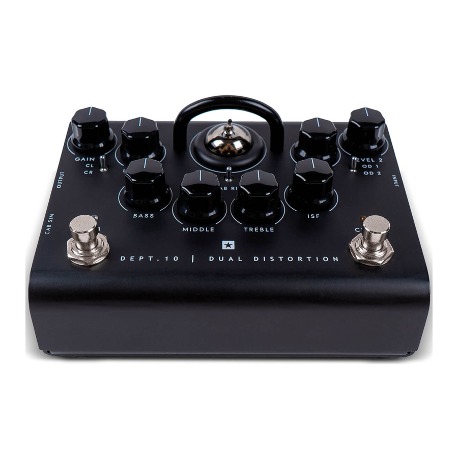
Top View

Dept. 10 Dual Drive Top View
- Input
Plug your guitar in here. Always use a good quality screened guitar lead. - Gain 1
This Gain control adjusts the amount of overdrive or distortion that Channel 1 will deliver. As the Gain control is increased clockwise (CW) the sound will become more overdriven moving through crunch tones until, at its maximum position, a full crunch tone is reached. - Level 1
This Level control sets the overall level or volume from Channel 1 of the pedal. It should be used in conjunction with the Gain 1 control to achieve the exact type of drive you require. Generally speaking, at lower Gain settings, the Volume will be increased and at higher Gain settings the Volume should be decreased. - Channel 1 Clean/Crunch Mode Switch
This switch enables Channel 1 to be set up as a Clean or Crunch channel. The Crunch channel can also be used as a clean boost by running the level high and the gain low. This will add further saturation to an already overdriven amplifier. - Bass
The Bass control adjusts the amount of low end frequencies in your tone. This pedal has an advanced tone shaping circuit (shared by Channel 1 and Channel 2) which allows the tone to be tight and cutting, counter clockwise (CCW), to warm and thumping (CW). - Middle
The Middle control adjusts the amount of middle frequencies in your tone. The middle frequencies are particularly important in getting the amount of 'body' your tone has. With the Middle control set to its minimum position (fully CCW) the sound will be aggressive and scooped, this is a tone ideal for aggressive rhythm playing. As the Middle control is increased (CW) the amount of 'body' is increased, which is more suitable for sustained lead guitar tones. - Treble
The treble control allows exact adjustment of the treble frequencies within the sound. At low settings (CCW) the sound will be warm and darker in character. As the Treble control is increased (CW) the sound will become brighter. At the maximum settings the sound will be aggressive and cutting. - ISF (Infinite Shape Feature)
The patented ISF control works in conjunction with the Bass, Middle and Treble controls. It allows you to choose the exact tone signature you prefer. Fully CCW is a more American characteristic with a tight bottom end and more aggressive middle, and fully CW is a British characteristic which is more 'woody' and less aggressive. See illustration below.
We recommend that to start with the ISF is set to half way and the Bass, Middle and Treble are set to taste. Then try gradually adjusting the ISF CW and CCW until you find the sound you prefer.

- Gain 2
This Gain control adjusts the amount of overdrive or distortion that Channel 2 will deliver. As the Gain control is increased (CW) the sound becomes more overdriven moving through crunch tones until, at its maximum position, a full distorted lead tone is reached. - Level 2
This Level control sets the overall level or volume from Channel 2 of the pedal. It should be used in conjunction with the Gain 2 control to achieve the exact type of drive you require. Generally speaking, at lower Gain settings, the Volume will be increased and at higher Gain settings the Volume should be decreased. - Cab Rig Switch
Select one of three Cab Rig environments. You can deep edit and load in your own Cab Rig settings using the free Architect software. - Valve Guard
Through this guard you can see the ECC83 valve at the heart of your pedal.


Do not attempt to remove the fixing screws or guard. No user serviceable parts inside.
- Channel 2 Overdrive 1/Overdrive 2 Mode Switch
This switches Channel 2 between Overdrive 1 or Overdrive 2 voicing.
Overdrive 2 gives more gain and saturation with a slight a lift in presence, achieving a great sustaining lead tone. - Output
This output is designed for connection to the input of other pedals or the input of a valve solid state, digital or hybrid amplifier. For best noise performance we recommend you place the overdrive pedal first in the effects chain. The built-in buffer/line driver is perfect for preserving your tone when using long cables, or large pedalboards, even driving low impedance pedals like many wah-wahs. Always use a good quality screened guitar lead. - Cab Rig Output
Cab Rig is our next generation DSP speaker simulator that reproduces the sound and feel of a mic'd up guitar cab in incredible detail. Deep dive edit, make custom patches for your cabinet, microphone, power amp and more by plugging your pedal into our free Architect software via USB. This source will output the selected Cab Rig switch preset, Left = 1, Middle = 2 and Right = 3. This output has the selected Cab Rig preset applied. A DI signal can be selected within the Cab Rig software to bypass the cabinet simulation.
NOTE: The Cab Rig output is a fully stereo 6.35mm connection and should only be used with a stereo jack. Cab Rig output also features a low noise and low distortion headphone driver circuit which can drive all standard headphone impedances and can be used for silent practice.
Download Architect here: https://www.blackstaramps.com/uk/architect

- Channel 1 On / Off LED
When the WHITE LED is on Channel 1 is on. When the LED is not on, Channel 1 is off. - Channel 1 On / Off Footswitch
Press this switch to turn Channel 1 on or off. - Channel 2 On / Off LED
When the RED LED is on Channel 2 is on. When the LED is not on, Channel 2 is off. - Channel 2 On / Off Footswitch
Press this switch to turn Channel 2 on or off.

Rear View

Dept. 10 Dual Drive Rear View
- FX Loop Send
Connect the (mono) input of an external effects unit here. Insert any external effects you want to keep clean such as reverb, delay, or modulation. - FX Loop Return
Connect the (mono) output of an external effects unit here. - DC Inlet
For the input of the 9V DC / 500mA adaptor supplied. Only use the included power supply. - USB Audio Output
Plug a USB cable in here to connect the amplifier to a Windows PC or Mac. The amplifier will appear on a personal computer as an audio capture device within recording software. This output has the selected Cab Rig preset applied. A DI signal can be selected within the Cab Rig software to bypass the cabinet simulation. - XLR Line / DI Output
A balanced output for connection to a PA, mixing desk or interface for recording and monitoring. This source will output the selected Cab Rig switch preset. This output has the selected Cab Rig preset applied. A DI signal can be selected within the Cab Rig software to bypass the cabinet simulation.
Technical Specification
DEPT. 10 DUAL DISTORTION
Power: 9V DC
Maximum Current Draw: 500mA
Valve: 1 x ECC83 / 12AX7
Input Impedance: 1MΩ
Output Impedance: < 1kΩ
Weight (kg): 0.63
Dimensions (mm): 157(W) x 76(H) x 117(D)
DC Adaptor: PSU-500 supplied (9VDC 500mA tip negative)
IMPORTANT SAFETY INSTRUCTIONS
- Read these instructions.
- Keep these instructions.
- Heed all warnings.
- Follow all instructions.
- Do not use this apparatus near water.
- Clean only with a dry cloth.
- Do not block any ventilation openings.
- Install in accordance with the manufacturer's instructions.
- Do not install near any heat sources such as radiators, heat registers, stoves, or other apparatus (including amplifiers) that produce heat.
- Do not defeat the safety purpose of the polarized or grounding-type plug. A polarized plug has two blades with one wider than the other. A grounding type plug has two blades and a third grounding prong. The wide blade or the third prong are provided for your safety. If the provided plug does not fit into your outlet, consult an electrician for replacement of the obsolete outlet.
- Protect the power cord from being walked on or pinched particularly at plugs, convenience receptacles, and the point where they exit from the apparatus.
- Only use attachments/accessories specified by the manufacturer.
- Unplug this apparatus during lightning storms or when unused for long periods of time.
- Refer all servicing to qualified service personnel. Servicing is required when the apparatus has been damaged in any way, such as power-supply cord or plug is damaged, liquid has been spilled or objects have fallen into the apparatus, the apparatus has been exposed to rain or moisture, does not operate normally, or has been dropped.
"TO COMPLETELY DISCONNECT THIS APPARATUS FROM THE AC MAINS, DISCONNECT THE POWER SUPPLY CORD PLUG FROM THE AC RECEPTACLE".


"TO REDUCE THE RISK OF FIRE OR ELECTRIC SHOCK, DO NOT EXPOSE THIS APPARATUS TO RAIN OR MOISTURE AND OBJECTS FILLED WITH LIQUIDS, SUCH AS VASES, SHOULD NOT BE PLACED ON THIS APPARATUS".
 This symbol is intended to alert the user to the presence of important operation and maintenance (servicing) instructions in the literature accompanying the appliance.
 This symbol is intended to alert the user to the presence of uninsulated "dangerous voltage" within the product's enclosure that may be of sufficient magnitude to constitute a risk of electric shock to persons.

RISK OF ELECTRIC SHOCK
DO NOT OPEN
Important safety information!
READ THE FOLLOWING INFORMATION CAREFULLY. SAVE ALL INSTRUCTIONS FOR FUTURE REFERENCE!
Follow all warnings and instructions marked on the product!

High internal operating voltages.
Do not open the equipment case. There are no user serviceable parts in this equipment. Refer all servicing to qualified service personnel.
Clean only with a dry cloth.
Condensation can form on the inside of an amplifier if it is moved from a cold environment to a warmer location. Before switching the unit on, it is recommended that the unit be allowed to reach room temperature.
Unauthorised modification of this equipment is expressly forbidden by Blackstar Amplification Ltd.
Never push objects of any kind into ventilation slots on the equipment casing.
Do not expose this apparatus to rain, liquids or moisture of any type.
Avoid placing vessels filled with liquid on top of the amplifier.
Do not place this product on an unstable trolley, stand or table. The product may fall, causing serious damage to the product or to persons!
Do not cover or block ventilation slots or openings.
This product should not be placed near a source of heat such as a stove, radiator, or another heat producing amplifier.
Use only the supplied power adaptor which is compatible with the mains voltage supply in your area.
The power supply adaptor should always be handled carefully and should be replaced if damaged in any way.
Never break off the earth (ground) pin on the power supply adaptor.
The power supply adaptor should be unplugged when the unit is to be unused for long periods of time.
Before the unit is switched on, the loudspeaker should be connected as described in the handbook using the lead recommended by the manufacturer.
Always replace damaged fuses with the correct rating and type.
Never disconnect the protective mains earth connection.
High loudspeaker levels can cause permanent hearing damage. You should therefore avoid the direct vicinity of loudspeakers operating at high levels. Wear hearing protection if continuously exposed to high levels.
If the product does not operate normally when the operating instructions are followed, then refer the product to a qualified service engineer.
Only suitable for safe use under non-tropical climate conditions. Maximum ambient temperature for operation: 35°C
Always make sure that the power adaptor is connected to a socket/outlet with an earthed connection.
Mains Voltage: 100-240V~ 50/60Hz.
This amplifier is only designed and evaluated for safety at a maximum altitude of 2000m.
The U.S. Government´s Occupational Safety and Health Administration (OSHA) has specified the following permissible noise level exposures:
| Duration Per Day In Hours | Sound Level dBA, Slow Response |
| 8 | 90 |
| 6 | 92 |
| 4 | 95 |
| 3 | 97 |
| 2 | 100 |
| 1½ | 102 |
| 1 | 105 |
| ½ | 110 |
| ¼ or less | 115 |
According to OSHA, any exposure in excess of the above permissible limits could result in some hearing loss.
Ear plug protectors in the ear canals or over the ears must be worn when operating this amplification system in order to prevent a permanent hearing loss if exposure is in excess of the limits as set forth above. To ensure against potentially dangerous exposure to high sound pressure levels, it is recommended that all persons exposed to equipment capable of producing high sound pressure levels such as this amplification system be protected by hearing protectors while this unit is in operation.
Blackstar Amplification Ltd, Beckett House, 14 Billing Road, Northampton, NN1 5AW, UK
For the latest information go to: www.blackstaramps.com
Whilst the information contained herein is correct at the time of publication, due to our policy of constant improvement and development, Blackstar Amplification Ltd reserves the right to alter specifications without prior notice.
Documents / Resources
References
Download manual
Here you can download full pdf version of manual, it may contain additional safety instructions, warranty information, FCC rules, etc.
Advertisement


Need help?
Do you have a question about the DEPT. 10 DUAL DISTORTION and is the answer not in the manual?
Questions and answers