
Related Manuals for Embedded Artists IoT Mini Prototype Board


Summary of Contents for Embedded Artists IoT Mini Prototype Board
- Page 1 IoT Mini Prototype Board - User's Manual Copyright 2018 © Embedded Artists AB IoT Mini Prototype Board with LPC54018 IoT Module EA2-USG-0702 v1.0 Rev A...
- Page 2 Embedded Artists Disclaimer Embedded Artists AB makes no representation or warranties with respect to the contents hereof and specifically disclaim any implied warranties or merchantability or fitness for any particular purpose.
-
Page 3: Table Of Contents
Powering, Current Measurement and Battery Charger ePaper Display Interface 4 Getting Started with NXP SDK Initial Instructions from NXP to Get Started 5 Explore the IoT Mini Prototype Board SW Installation of Embedded Artists' Software Bundle Software Common to all Projects 5.2.1 Support for ePaper Display 5.2.2... -
Page 4: Document Revision History
IoT Mini Prototype Board - User's Manual Page 4 1 Document Revision History Revision Date Description 2018-05-15 Initial version with software instructions. 2018-06-04 Added information about hardware design. 2018-06-11 Added correct pictures and information about ePaper mounting. Copyright 2018 © Embedded Artists AB... -
Page 5: Board Overview
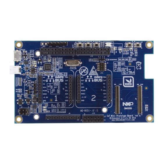
Page 5 2 Board Overview The IoT Mini Prototype Board has been designed to be a easy-to-use prototyping platform for the LPC54018 IoT Module - to goal is to get up-and-running quickly with your prototyping involving! The board has the following features: ... - Page 6 IoT Mini Prototype Board - User's Manual Page 6 On the bottom side, the optional ePaper display can be mounted. Location for optional ePaper display Figure 2 – IoT Mini Prototype Board, Bottom Side Copyright 2018 © Embedded Artists AB...
-
Page 7: Hardware Design
Note that it is easy to damage the DF40C connectors with improper handling.. The picture below illustrates how it looks like when the LPC54018 IoT Module has been mounted. Figure 3 – IoT Mini Prototype Board with LPC54018 IoT Module Mounted Copyright 2018 © Embedded Artists AB... -
Page 8: Arduino Compatible Expansion Interface
IoT Mini Prototype Board - User's Manual Page 8 Arduino Compatible Expansion Interface Page 6 of the schematic contains the Arduino shield connectors, J8, J14, J15 and J16. Three of these (J14, J15 and J16) are double row connectors, which are not part of the Arduino shield connector standard, but these extra pins have been added to be compatible with some of NXP's LPCXpresso and related add-on boards. -
Page 9: Click Module Compatible Expansion Interface
IoT Mini Prototype Board - User's Manual Page 9 J14, pin 3 P3_23-FC2_SDAX Note: Signals is also connected to both Click Modules J14, pin 1 P3_24-FC2_SCLX Note: Signals is also connected to both Click Modules Note that due to a schematic error on rev A boards, pin 6 of J15 is grounded. This means that the Arduino signal AIN2 cannot be used - and is grounded. - Page 10 IoT Mini Prototype Board - User's Manual Page 10 to the Arduino interface Output J5, pin 4 P3_27-FC4_TXD Note: Signals is also connected to Click Module #2 and to the Arduino interface Output J5, pin 5 P3_24-FC2_SCLX Note: Signals is also connected to Click Module #2 and...
-
Page 11: 3-Axis Accelerometer
IoT Mini Prototype Board - User's Manual Page 11 Note: Signals is also connected to Click Module #1 and to the Arduino interface Output J7, pin 4 P3_27-FC4_TXD Note: Signals is also connected to Click Module #1 and to the Arduino interface... -
Page 12: Dap-Link Debug Interface
Page 7 of the schematic contains the powering solution. There is a 3.3V power supply, capable of supplying up to 700mA to the IoT Mini Prototype Board and LPC54018 IoT Module together. There are four ways to power the board: ... -
Page 13: Epaper Display Interface
Figure 4 – ePaper Display, Two Layers of Double-Sided Tape on Bottom Side Open the connector’s flip lock carefully. It is found on the bottom side of the IoT Mini Prototype Board. Insert the flat cable of the ePaper display carefully. Close the connector’s flip lock carefully. Remove the upper protection layer of the double-sided tape, align the display and press the display carefully to the PCB. - Page 14 IoT Mini Prototype Board - User's Manual Page 14 Figure 5 – ePaper Display Mounted on Bottom Side Note that ePaper displays must be refreshed regularly. Over time the contrast will become lower. The picture below illustrates how the display looks like after about 24 hours. The red color starts to “bleed” in the display area.
-
Page 15: Getting Started With Nxp Sdk
Secondly, follow the instructions in this document to download and compile the code specific for the IoT Mini Prototype board. This part is covered in chapter 5 . Initial Instructions from NXP to Get Started To start with, you need to download and install: ... - Page 16 Page 16 Follow all the steps in the online guide up to 3.6 Success! You are now ready to install and use the software specific to the IoT Mini Prototype Board, see next chapter. Copyright 2018 © Embedded Artists AB...
-
Page 17: Explore The Iot Mini Prototype Board Sw
After verifying that everything works by following the guide in the previous chapter it is now time to install the example projects specific for the IoT Mini Prototype Board. 1. Start by clicking the Import project(s) from file system… link in the Quickstart Panel in MCUXpresso. - Page 18 IoT Mini Prototype Board - User's Manual Page 18 3. In the online guide that was followed in section 4.1 one file was generated (aws_clientcredential_keys.h) and one was updated (aws_clientcredential.h). The files contain the wifi settings and the certificates that are needed to connect to AWS. Copy those files from the amazon-freertos/include/ directory in the lpc54018iotmodule_aws_shadow_wifi_qspi_xip project into the same location in the newly imported LPC54018_IoT_Base_plus_aws project.
-
Page 19: Software Common To All Projects
Board. 5.2.1 Support for ePaper Display The IoT Mini Prototype Board has a connector to an optional (bought separately) 2.66" ePaper display that can display red in addition to the standard black/white. The display requires two different libraries: Pervasive_EPD_BoosterPack2 which is the hardware abstraction layer ... -
Page 20: Support For Click Modules And Arduino Shields
Support for Click Modules and Arduino Shields The IoT Mini Prototype Board has two connectors for Click modules and one for Arduino shield. The example projects come with skeleton code to make it easier to plug in software for any of the expansions. -
Page 21: Other Tasks
It should be modified to suit the real application. By default it contains the status of the User button (the button closest to the corner of the IoT Mini Prototype Board). Next is a set of defines for the changes that can be made to the shared data: #define DS_MSG_CHANGED (1<<0) - Page 22 IoT Mini Prototype Board - User's Manual Page 22 FreeRTOS replaced with the setup from the SDK's shadow_wifi_qspi_xip example The wifi module on the IoT board is enabled and used. SSID and password must be configured in amazon-freertos/include/aws_clientcredential.h for it to work ...
- Page 23 IoT Mini Prototype Board - User's Manual Page 23 4. Click the myShadowThing box to open the detailed view: 5. Go to the Shadow page to view the data from your registered IoT module updates: Copyright 2018 © Embedded Artists AB...
- Page 24 IoT Mini Prototype Board - User's Manual Page 24 6. Go to the Interact page to see some different URLs to use when communicating with the Thing. To send a string to the IoT module we need the update URL: The URL is $aws/things/myShadowThing/shadow/update 7.
- Page 25 Open the Activity page and look for any error messages Pressing the User Button on the IoT Mini Prototype Board should result in an update on the Shadow page showing that the button is pressed. Copyright 2018 © Embedded Artists AB...
-
Page 26: Aws Cli
IoT Mini Prototype Board - User's Manual Page 26 6 AWS CLI The AWS CLI is an open source tool built on top of the AWS SDK for Python (Boto) that provides commands for interacting with AWS services. With minimal configuration, you can start using all of the functionality provided by the AWS Management Console from your favorite terminal program. - Page 27 IoT Mini Prototype Board - User's Manual Page 27 $ aws iot-data get-thing-shadow --thing-name myShadowThing outfile The result is a file named outfile that contains the json data. With some formatting it looks like this: "state":{ "desired":{ "task":"Shd-IOT-0", "msg":"Hello World!", "button":"Released"...
- Page 28 X-ON Electronics Largest Supplier of Electrical and Electronic Components Click to view similar products for category: Development Boards & Kits - ARM Click to view products by manufacturer: Other Similar products are found below : SAFETI-HSK-RM48 PICOHOBBITFL CC-ACC-MMK-2443 TWR-MC-FRDMKE02Z EVALSPEAR320CPU EVB-SCMIMX6SX MAX32600-KIT# TMDX570LS04HDK TXSD-SV70 OM13080UL EVAL-ADUC7120QSPZ OM13082UL TXSD-SV71 YGRPEACHNORMAL OM13076UL PICODWARFFL YR8A77450HA02BG 3580 32F3348DISCOVERY ATTINY1607 CURIOSITY NANO PIC16F15376 CURIOSITY NANO BOARD PIC18F47Q10 CURIOSITY NANO VISIONSTK-6ULL V.2.0 80-001428 DEV-17717...
Need help?
Do you have a question about the IoT Mini Prototype Board and is the answer not in the manual?
Questions and answers