
Related Manuals for Embedded Artists LPCXpresso Base Board


Summary of Contents for Embedded Artists LPCXpresso Base Board
- Page 1 B - User’s Guide LPCXpresso Base Board Copyright 2011 © Embedded Artists AB LPCXpresso Base Board Rev B User’s Guide Get Up-and-Running Quickly and Start Developing Your Applications On Day 1! EA2-USG-1001B Rev B...
- Page 2 Embedded Artists AB. Disclaimer Embedded Artists AB makes no representation or warranties with respect to the contents hereof and specifically disclaim any implied warranties or merchantability or fitness for any particular purpose. Information in this publication is subject to change without notice and does not represent a commitment on the part of Embedded Artists AB.
-
Page 3: Table Of Contents
LPCXpresso Base Board rev B - User’s Guide Page 3 Table of Contents 1 Document Revision History 2 Introduction Features ESD and Handling Precaution CE Assessment Other Products from Embedded Artists 2.4.1 Design and Production Services 2.4.2 OEM / Education / QuickStart Boards and Developer’s Kits... - Page 4 LPCXpresso Base Board rev B - User’s Guide Page 4 4.4.1 OLED Display 4.4.2 Dual UART SC16IS752 – U19 USB Device Direct Digital IO 4.6.1 Push Button (BL) – SW3 4.6.2 Push Button (WAKEUP) – SW4 4.6.3 Quadrature Rotary Switch – SW5 4.6.4...
-
Page 5: Document Revision History
LPCXpresso Base Board rev B - User’s Guide Page 5 1 Document Revision History Revision Date Description PA1-PA2 2010-01-20 First incomplete version. 2010-01-24 Second, still incomplete version. 2010-01-25 Added more information about jumper settings. 2010-01-26 Added information to the Getting Started Chapter. -
Page 6: Introduction
6 mbed and LPC1xxx Differences. Features The LPCXpresso Base Board makes it possible for you to get started with experiments and prototyping immediately with the LPCXpresso Board. The LPCXpresso Base Board can also be used together with the mbed module. -
Page 7: Esd And Handling Precaution
LPCXpresso Base Board. Due to the nature of the LPCXpresso Base Board – an evaluation board not for integration into an end- product – fast transient immunity tests and conducted radio-frequency immunity tests have not been executed. -
Page 8: Design And Production Services
2.4.1 Design and Production Services Embedded Artists provide design services for custom designs, either completely new or modification to existing boards. Specific peripherals and I/O can be added easily to different designs, for example, communication interfaces, specific analog or digital I/O, and power supplies. Embedded Artists has a broad, and long, experience in designing industrial electronics in general and with NXP’s... -
Page 9: Getting Started
IDE and more information that is related to LPCXpresso. Initial Preparation The LPCXpresso Base Board is delivered with two pin lists. These pin lists must be soldered onto your LPCXpresso target board before it can be used with the LPCXpresso Base Board. Figure 1 and Figure 2 shows how the pin lists are soldered onto an LPCXpresso LPC1343 board. -
Page 10: Board Powering
Board Powering The LPCXpresso Base Board shall be powered from a PC via the included USB cable (mini-B to A cable). Up to 500mA can be drawn from the USB port. Note that not all PC USB ports supply the specified top current (500 mA). -
Page 11: Console Interface Via Usb-To-Uart Bridge
(search for a FT232R driver for your operating system). When the LPCXpresso Base Board is connected to the PC (via an USB cable) the PC will ask for a driver. Unpack/unzip the downloaded driver file and browse to the position of the driver files. After successful driver installation, a COM port will be created. - Page 12 LPCXpresso Base Board rev B - User’s Guide Page 12 Ports Figure 5 – Device Manager Dialog The new COM port (USB Serial Port) will be listed under the Ports list. Right-click on the new USB Serial Port and select Properties, as illustrated in Figure 6 below.
- Page 13 LPCXpresso Base Board rev B - User’s Guide Page 13 Select 115200 bits per second, 8 data bits, none parity, 1 stop bit, and none flow control, as illustrated in Figure 7 below. Then select Advanced settings. Please note that different application programs can use different baudrate settings for the serial channel.
-
Page 14: Usb Driver Behavior
LPCXpresso Base Board rev B - User’s Guide Page 14 Finally it is time to test if you have successfully installed and configured the USB Serial Port. Start a terminal program. Connect to the correct COM port, with 115200 bits per second, 8N1, no flow control. -
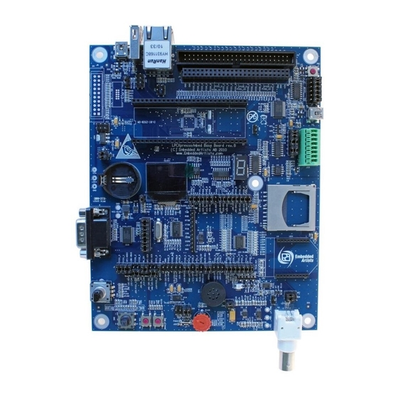
Page 15: Main Components
LPCXpresso Base Board rev B - User’s Guide Page 15 Main Components Figure 9 below illustrates the main component of the LPCXpresso Base Board. The number inside parenthesis (pX) indicate on which schematic page (X) the components can be found. USB Host interface... -
Page 16: Default Jumper Positions
3.6.1 Illegal Jumper Combinations The LPCXpresso Base Board has multiple peripherals that connect to the LPC1xxx processor. There is a shortage of pins to connect to and in a few cases different peripherals must share pins. See chapter 5 for an overview of all connections. -
Page 17: Import Sample Applications
– Drivers for peripherals on the LPC1343/LPC1114 microcontroller Lib_MCU – Drivers for peripherals on the Embedded Artists LPCXpresso Base Board Lib_EaBaseBoard – ChaN’s FAT Fs module ported to the LPCXpresso base Board (used with the Lib_FatFs_SD MMC/SD card interface). Copyright 2011 © Embedded Artists AB... - Page 18 LPCXpresso Base Board rev B - User’s Guide Page 18 Figure 11 – Import project Figure 12 – LPCXpresso Import Dialog Copyright 2011 © Embedded Artists AB...
- Page 19 LPCXpresso Base Board rev B - User’s Guide Page 19 Figure 13 – LPCXpresso imported projects Copyright 2011 © Embedded Artists AB...
-
Page 20: Demo Application
Page 20 Figure 14 – LPCXpresso Build button Demo Application A suitable application to start with when checking the functionality of the LPCXpresso Base Board is the application called . This application is using several of the peripherals, such as the... -
Page 21: Program Download
This section describes how you generate the binary file, adds the necessary checksum to the binary file and downloads the file to the target while it is mounted on the LPCXpresso Base Board. For this to work you need to have some jumpers correctly set. If you have all jumpers in default position as described in section 3.6 USB boot mode will work;... - Page 22 LPCXpresso Base Board rev B - User’s Guide Page 22 USB interface – jumpers described in section 4.5. SW3 button – jumper described in section 4.6.1. You also need to make sure that the BL_EN signal is connected to GPIO_24-BL_EN signal, see section 4.1.1.1 and Figure 22.
- Page 23 LPCXpresso Base Board rev B - User’s Guide Page 23 Figure 16 – LPCXpresso IDE Create a Binary File Copyright 2011 © Embedded Artists AB...
- Page 24 LPCXpresso Base Board rev B - User’s Guide Page 24 Figure 17 – LPCXpresso IDE Open Command Prompt Figure 18 – Mass Storage Device Copyright 2011 © Embedded Artists AB...
-
Page 25: Using Uart (Isp) Boot Mode For Lpc1343 / 1227 / 11C24 / 11U14 / 1114
LPCXpresso Base Board rev B - User’s Guide Page 25 3.9.3 Using UART (ISP) Boot Mode for LPC1343 / 1227 / 11C24 / 11U14 / 1114 The LPC1343 / 1227 / 11C24 / 11U14 / 1114 all supports In-System Programming (ISP) from the UART. -
Page 26: Using Uart (Isp) Boot Mode For Lpc176X
However, if UART channel#0 is connected to a serial channel (RS232 or USB-to-UART bridge) via an external adapter board (note: not provided with the LPCXpresso Base Board) it is possible to use Flash Magic to download program code to the LPC176x. -
Page 27: Peripherals And Jumper Settings
Page 27 4 Peripherals and Jumper Settings This chapter contains information about the peripherals of the LPCXpresso Base Board and how to set the different jumpers on the board. The schematic can be downloaded in pdf from the support page, and is recommended to have printed out while reading this chapter. - Page 28 LPCXpresso Base Board rev B - User’s Guide Page 28 4.1.1.1 ISP-option The USB-to-UART bridge can automatically activate the bootload mode of the LPC1xxx. A program image can then be downloaded via the UART channel. The RTS signal can pull pin GPIO_24-BL_EN low, which enabled bootload mode after reset.
-
Page 29: Rs422/485 - U6
LPCXpresso Base Board rev B - User’s Guide Page 29 4.1.2 RS422/485 – U6 To connect the UART to the RS422/485 transceiver, insert two jumpers in J7 (schematic page 11), as illustrated in Figure A RS422/485 transceiver must control the Rx- and Tx-paths. - Page 30 LPCXpresso Base Board rev B - User’s Guide Page 30 4.1.2.1 RS422 In RS422, the Rx- and Tx-paths must be controlled independently since both can be active simultaneously (full duplex). Rx-enable is controlled by GPIO_28 (insert J17) and is active low. Tx-enable is controlled by GPIO_18 (insert J18 in position 2-3) and is active high.
- Page 31 LPCXpresso Base Board rev B - User’s Guide Page 31 4.1.2.2 RS485 In RS485, the Rx- and Tx-paths can be controlled together since they are not active simultaneously (half duplex). GPIO_28 controls both Rx and Tx. When GPIO_28 is high, Tx is enabled, and when GPIO_28 is low, Rx is enabled.
-
Page 32: Rf-Module - U23
LPCXpresso Base Board rev B - User’s Guide Page 32 4.1.3 RF-module – U23 To connect the UART to the RF-module, U23 (interface socket for XBee® modules from Digi International Inc.), insert two jumpers in J7 (schematic page 11), as illustrated in Figure Figure 28 –... -
Page 33: I2C
LPCXpresso Base Board rev B - User’s Guide Page 33 The LPC1xxx I2C-bus is connected to the following peripherals: E2PROM (24LC08), see schematic page 8, U11. See subsection 4.2.1 Port expander (PCA9532), see schematic page 8, U12. See subsection 4.2.2 ... -
Page 34: Light Sensor, Isl29003 - U13
LPCXpresso Base Board rev B - User’s Guide Page 34 4.2.3 Light Sensor, ISL29003 – U13 U13 is always connected to the I2C-bus.There is an interrupt output that can be connected to GPIO_33 via J36 (schematic page 8). See Figure 31 for details. Make sure there is no other driver on the GPIO_33 signal when using it as interrupt signal. -
Page 35: Spi
LPCXpresso Base Board rev B - User’s Guide Page 35 The LPC1xxx SPI-bus is connected to the following peripherals: Dataflash (AT45DB016), see schematic page 9, U15. See subsection 4.3.1 7-segment display via shift register, see schematic page 9, U16. See subsection 4.3.2 ... -
Page 36: Dataflash, At45Db016 - U15
LPCXpresso Base Board rev B - User’s Guide Page 36 4.3.1 Dataflash, AT45DB016 – U15 The Dataflash chip, U15, can be connected to the SPI-bus. Insert all four jumpers in J38 (schematic page 9), as illustrated in Figure 33, in order to connect all SPI signals to U15. -
Page 37: 7-Segment Display Via Shift Register - U16
LPCXpresso Base Board rev B - User’s Guide Page 37 4.3.2 7-segment display via shift register – U16 The 7-segment display shift register, U16, can be connected to the SPI-bus. Insert three (of the four) jumpers in J41 (schematic page 9), as illustrated in Figure 35, in order to connect the SPI signals to U16. -
Page 38: Sd/Mmc Memory Card Interface
LPCXpresso Base Board rev B - User’s Guide Page 38 4.3.3 SD/MMC memory card interface The SD/MMC memory card interface connector, J40, can be connected to the SPI- bus. Insert all five jumpers in J39 (schematic page 9), as illustrated in Figure 37, in order to connect all SPI signals to J40 (and ultimately J39, pin 9-10. -
Page 39: I2C/Spi
LPCXpresso Base Board rev B - User’s Guide Page 39 I2C/SPI There are two peripherals, as presented in the I2C and SPI sections, which can be connected to either the I2C or the SPI interfaces. These two peripherals have both I2C and SPI interfaces. The SPI interface has higher data rate but require more signals. -
Page 40: Dual Uart Sc16Is752 - U19
LPCXpresso Base Board rev B - User’s Guide Page 40 4.4.2 Dual UART SC16IS752 – U19 The dual UART SC16IS752, U19 (schematic page 10), can be connected either to the SPI-bus or the I2C-bus. For I2C interface (default), insert jumpers in J48 pin 2-3, J49 (schematic page 10), as illustrated in Figure 40. -
Page 41: Usb Device
LPCXpresso Base Board rev B - User’s Guide Page 41 USB Device The LPC176x/LPC1343/11U14 USB interface can be connected to mini-B USB connector (X1, on schematic page 5). Note that the LPC1114 does not contain any USB interface. Also note that LPC11U14 has a mini-B USB connector on the LPCXpresso target board which is better to use. -
Page 42: Direct Digital Io
LPCXpresso Base Board rev B - User’s Guide Page 42 Direct Digital IO The LPC1xxx is connected to a number of peripherals directly via the general purpose digital input/output pins: 5-key joystick), see schematic page 6, SW2. Directly connected to GPIO_8, GPIO_9, GPIO_10, GPIO_31 and GPIO_32 ... -
Page 43: Temperature Sensor - U7
LPCXpresso Base Board rev B - User’s Guide Page 43 4.6.4 Temperature Sensor – U7 The output signal from U7 (schematic page 6) can be connected to either GPIO_4 or GPIO_17. J25 selects which. See Figure 45 for jumper details. -
Page 44: Pwm Low Pass Filter To Analog Signal, U9
LPCXpresso Base Board rev B - User’s Guide Page 44 4.7.2 PWM Low Pass Filter to Analog Signal, U9 Insert a jumper in J31 to connect signal GPIO_14 to the low pass filer implemented around U9. The PWM input signal and the low pass filtered result are available on pads. See Figure 47 for details. -
Page 45: Direct Analog Io
LPCXpresso Base Board rev B - User’s Guide Page 45 Direct Analog IO The LPC1xxx is connected to a number of peripherals directly via analog input pins: Trimming potentiometer (R105), see schematic page 7. See subsection 4.9.1 BNC input (X2 and U8), see schematic page 7. See subsection 4.9.2 4.9.1... - Page 46 LPCXpresso Base Board rev B - User’s Guide Page 46 Left: DC coupling Right: AC coupling J30 insert: x10 J30 open: x1 Figure 50 – Jumper Setting: BNC analog input, U8 Copyright 2011 © Embedded Artists AB...
-
Page 47: Lpc176X And Mbed: Usb Host, Can And Ethernet
LPCXpresso Base Board rev B - User’s Guide Page 47 4.10 LPC176x and mbed: USB Host, CAN and Ethernet There are three peripherals that are only valid for the LPC176x and mbed module: USB Host (J60), see schematic page 5. See subsection 4.10.1 ... -
Page 48: Ethernet - J19
LPCXpresso Base Board rev B - User’s Guide Page 48 4.10.3 Ethernet – J19 The Ethernet connector (J19, schematic page 5) is connected to the socket for the LPC176x/mbed module. The Ethernet PHY is on the LPCXpresso LPC176x/mbed module. There are two LEDs inside the J19. Note that the LEDs are not controlled by the Ethernet PHY. -
Page 49: Usage Of Cpu Pins
B - User’s Guide LPCXpresso Base Board Copyright 2011 © Embedded Artists AB 5 Usage of CPU Pins The table below gives details about what pins are used for the different peripherals. The yellow colored fields signal where there are problems for the mbed module. See chapter 6 for details about the differences between mbed modules and LPCXpresso Boards. -
Page 50: Expansion Connectors
Left side Right side Figure 54 – LPCXpresso Base Board Expansion Connectors (J5, J6) The text on the pcb indicates where the different signals can be accessed. The left side of J6 is also valid as a left side of J5, and similar is the right side of J5 also valid as right side of J6. - Page 51 LPCXpresso Base Board rev B - User’s Guide Page 51 Note that the pin names/text is valid for the LPC1343 (for which the LPCXpresso Base Board was originally designed). Gradually more and more LPCXpresso target boards have been added and signal names on the schematic have changed to generic names. Be sure to understand the connection between the two naming conventions.
-
Page 52: Mbed And Lpc1Xxx Differences
Most pins can have the same functionality, like UART, I2C, SPI, analog input, etc. Figure 55 illustrates how the mbed is mounted on the LPCXpresso Base Board. It shall be placed on the upper most position in J4 when the base board is oriented as in the picture below. - Page 53 Insert J58 and signal GPIO_2-MISO can be used for control. Note that signal naming above follow LPCXpresso base board naming, which is not the same naming as the mbed module has. See Figure 56 for details where to find J58.
-
Page 54: Lpcxpresso Lpc11C24
LPCXpresso Base Board rev B - User’s Guide Page 54 LPCXpresso LPC11C24 The LPC11C24 has fewer available GPIO pins since the on-chip CAN transceiver requires some pins. There is an Excel sheet that can be downloaded with the pinning of all LPCXpresso modules. This... -
Page 55: Mechanical Dimensions
LPCXpresso Base Board rev B - User’s Guide Page 55 7 Mechanical Dimensions Figure 57 below contains a drawing of the board that includes mechanical measures. Important holes or center lines are marked with x,y coordinates in mil and mm. -
Page 56: Troubleshooting
The Board Behaves Strange The LPCXpresso Base Board shall be powered from a PC via the included USB cable (mini-B to A cable). Up to 500mA can be drawn from the USB port. Reason: The LPCXpresso Base Board and LPCXpresso LPC1xxx Board do not receive enough current. -
Page 57: Further Information
LPCXpresso Base Board rev B - User’s Guide Page 57 9 Further Information The LPC1xxx microcontrollers are complex circuits and there are a number of other documents with more information. The following documents are recommended as a complement to this document.
Need help?
Do you have a question about the LPCXpresso Base Board and is the answer not in the manual?
Questions and answers