
Related Manuals for HEIDENHAIN BC 110 BF


Summary of Contents for HEIDENHAIN BC 110 BF
- Page 1 Austauschanleitung Replacing Instructions BC 110 BF ID 374964-21 Als Ersatz für Replacing BC 110/B BC 110 BF ID 374964-01 06/2022...
- Page 2 Austauschanleitung......................................3 Replacing Instructions....................................15...
-
Page 3: Table Of Contents
Austauschanleitung BC 110 BF Inhalt Bedeutung der verwendeten Symbole Vorbereitende Maßnahmen Demontage Anschlüsse und Bedienelemente Montage Prüfung... -
Page 4: Bedeutung Der Verwendeten Symbole
Bedeutung der verwendeten Symbole Sicherheitshinweise Beachten Sie alle Sicherheitshinweise in dieser Austauschanleitung und in der Dokumentation Ihres Maschinenherstellers. Die Sicherheitshinweise sind wie folgt aufgebaut: HINWEIS Signalwort Kollisionsgefahr! Art der Gefährdung Wenn Sie ..., dann ... Folge bei Nichtbeachtung Sichere Position ... Anleitung zum Vermeiden von Gefährdungen In dieser Austauschanleitung finden Sie folgende Sicherheitshinweise: WARNUNG... - Page 5 Bedeutung der verwendeten Symbole In dieser Austauschanleitung finden Sie folgende Informationshinweise: Das Buchsymbol steht für einen Querverweis zu externen Dokumentationen, z. B. der Dokumentation Ihres Maschinenherstellers oder eines Drittanbieters. Das Informationssymbol steht für einen Tipp. Ein Tipp gibt wichtige zusätzliche oder ergänzende Informationen.
-
Page 6: Vorbereitende Maßnahmen
Vorbereitende Maßnahmen WARNUNG Unsachgemäße Ausführung von Wartungsarbeiten durch nicht entsprechend geschultes Personal Personen- oder Sachschäden Der Austausch ist von einer Fachkraft für Elektrik und Mechanik unter Beachtung der örtlichen Sicherheitsvorschriften vorzunehmen. Vor dem Austausch sind folgende Arbeitsschritte durchzuführen: Steuerung herunterfahren Maschine ausschalten Maschine gegen Wiedereinschalten sichern Spannungsfreiheit feststellen... -
Page 7: Demontage
Demontage Defekten Bildschirm ausbauen Alle Befestigungsschrauben an der Gerätefront lösen Bildschirm vorsichtig aus dem Bildschirmgehäuse ziehen Alle Steckverbindungen lösen und ggf. markieren Bildschirm vollständig herausnehmen... -
Page 8: Anschlüsse Und Bedienelemente
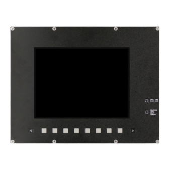
Anschlüsse und Bedienelemente Lage der Anschlüsse und Bedienelemente am BC 110BF, ID 374964-21... - Page 9 Anschlüsse und Bedienelemente Power Ein- und Ausschalten des Geräts Die Betätigung der Taste ist normalerweise nicht notwendig, da sich das Gerät nach dem Anlegen der Versorgungsspannung automatisch einschaltet. Status-LED Aus: Gerät ausgeschaltet, keine Versorgungsspannung Grün: Normalbetrieb Orange: Kein Videosignal OSD-Taste + Erhöhung der Einstellwerte in Untermenüs "Up"...
- Page 10 Anschlüsse und Bedienelemente Netzeingang Signaleingang 15-pol. HD-Buchse (analog) BC 110; EPC (VME) Signaleingang 9-pol. Buchse (TTL) BE 411; BE 412; BE 511 25-pol. Buchse (TTL) monochrom BE 110; BE 211; BE 311 15-pol. Buchse (TTL) BE 132; BE 212; BE 511; BE 512 15-pol.
-
Page 11: Montage
Montage Vorbereitende Maßnahmen bei Austausch eines BC 110B WARNUNG Spannungsführende Teile Personenschaden durch Stromschlag Spannungsfreiheit der Netzzuleitung sicherstellen Falls der BC 110BF als Ersatz für einen BC 110B eingesetzt werden soll, muss der Stecker am Netzkabel ersetzt werden. Alten Netzstecker von der Netzzuleitung entfernen Beiliegenden Kaltgeräte-Winkelstecker an der Netzzuleitung montieren... - Page 12 Montage Montage des Bildschirms Beiliegende Dichtungen umlaufend am hinteren Rand der Frontplatte des Austauschgeräts aufkleben Flachbandkabel (X8 9-polig, Stift) der Softkeyleiste mit dem Gegenstück im Bildschirmgehäuse verbinden Stecker 15-polig, Stift, dreireihig des beliegenden Adapterkabels mit X1 am BC 110BF verbinden Stecker 15-polig, Stift, zweireihig des beiliegenden Adapterkabels mit der Signalleitung im Bildschirmgehäuse verbinden Netzzuleitung mit X0 am BC 110BF verbinden Korrekte Einstellung der DIP-Schalter sicherstellen...
- Page 13 Bildschirms und zur fachgerechten Entsorgung finden Sie in der Betriebsanleitung des BC 110BF. Die Betriebsanleitung steht in der Infobase – Produktsuche für Experten (www.heidenhain.de) nach Eingabe der ID 374964-21 als PDF-Datei zum Download bereit. Die Erdungsklemme des BC 110BF muss nicht separat angeschlossen werden.
-
Page 14: Prüfung
Prüfung DIN VDE 0113 Teil 1 / EN 60204-1 Gemäß DIN VDE 0113 Teil 1 / EN 60204-1 müssen nach dem Austausch einer Komponente folgende Prüfungen durchgeführt werden: Übereinstimmung der elektrischen Ausrüstung mit der technischen Dokumentation Durchgängigkeit des Schutzleitersystems Funktionsprüfung Legen Sie diese Austauschanleitung in der technischen Dokumentation der Maschine ab und vermerken Sie die Änderungen. - Page 15 Replacing Instructions BC 110 BF Contents Meaning of the symbols used in these instructions Preparations Disassembly 10 Connectors and controls 11 Installation 12 Review...
-
Page 16: Meaning Of The Symbols Used In These Instructions
Meaning of the symbols used in these instructions Safety precautions Comply with all safety precautions indicated in these Replacing Instructions and in your machine tool builder’s documentation. The safety precautions have the following structure: NOTICE Signal word Danger of collision! Type of hazard If you ..., then ... - Page 17 Meaning of the symbols used in these instructions In these instructions, you will find the following informational notes: The book symbol represents a cross reference to external documentation, e.g. the documentation of your machine manufacturer or other supplier. The information symbol indicates a tip. A tip provides additional or supplementary information.
-
Page 18: Preparations
Preparations WARNING Improper execution of maintenance work by staff not trained appropriately Personal injury or property damage Replacement is to be conducted by a specialist for electrical and mechanical systems under compliance with local safety regulations. The following steps must be carried out before the replacement: Shut down the control Switch off the machine Take precautions against restart of the machine... -
Page 19: Disassembly
Disassembly Removing the defective screen Loosen all fastening screws on the front of the device Carefully pull the screen out of the housing Disconnect all plug connections and label them if necessary Remove screen entirely... -
Page 20: Connectors And Controls
Connectors and controls Positions of the connectors and controls on BC 110BF, ID 374964-21... - Page 21 Connectors and controls Power To switch the device on and off Usually it is not necessary to press this button, because the monitor is automatically switched on when the supply voltage is applied. Status LED Off: The device is switched off, no supply voltage Green: Normal operation Orange: No video signal OSD button +...
- Page 22 Connectors and controls Line input Signal input 15-pin HD socket (analog) BC 110; EPC (VME) Signal input 9-pin socket (TTL) BE 411; BE 412; BE 511 25-pin socket (TTL) monochrome BE 110; BE 211; BE 311 15-pin socket (TTL) BE 132; BE 212; BE 511; BE 512 15-pin socket (analog) EPC (VME) 15-pin socket (TTL)
-
Page 23: Installation
Installation Preparations when replacing a BC 110B WARNING Live electrical parts Personal injury due to electric shock Ensure that the power supply line is not under voltage If the BC 110BF is to be used as a replacement for a BC 110B, the connector on the power cable needs to be exchanged. Remove the old connector from the power cable Fit the enclosed inlet connector for non-heating appliances to the power cable... - Page 24 Installation Mounting the screen Attach the enclosed seal all around the rear edge of the front panel of the replacement unit Connect the ribbon cable (X8, 9-pin, male) of the soft-key row to its counterpart in the screen housing Connect the 15-pin, male, three-row connector of the enclosed adapter cable to X1 on the BC 110BF Connect the 15-pin, male, double row connector of the enclosed adapter cable to the signal line in the screen housing Connect the power cable to X0 on the BC 110BF Make sure that the positions of the DIP switches are correct...
- Page 25 The operating instructions are available for download in PDF format from the Infobase – Search for specific product (www.heidenhain.de) after entering ID 374964-21. The ground terminal of the BC 110 BF does not have to be connected additionally. Grounding is established via the grounding conductor of the power supply line.
-
Page 26: Review
Review DIN VDE 0113 part 1 / EN 60204-1 According to DIN VDE 0113 part 1 / EN 60204-1, the following examinations are required after a component has been exchanged: Compliance of the electrical equipment with the technical documentation Continuity of the grounding conductor system Functional test File these replacing instructions with the technical documentation of the machine and record all changes. - Page 27 ...
- Page 28 DR. JOHANNES HEIDENHAIN GmbH Dr.-Johannes-Heidenhain-Straße 5 83301 Traunreut, Germany +49 8669 31-0 +49 8669 32-5061 E-mail: info@heidenhain.de Technical support +49 8669 32-1000 Measuring systems +49 8669 31-3104 E-mail: service.ms-support@heidenhain.de NC support +49 8669 31-3101 E-mail: service.nc-support@heidenhain.de NC programming ...
Need help?
Do you have a question about the BC 110 BF and is the answer not in the manual?
Questions and answers