Table of Contents
Advertisement
Quick Links
Owner's Operator and Maintenance Manual
Get-U-Up
Lift
™
DEALER: This manual MUST be given to
the user of this device.
USER: BEFORE using this device, read this
manual and save for future reference.
For more information regarding
Invacare products, parts, and services,
please visit www.invacare.com
Download from Www.Somanuals.com. All Manuals Search And Download.
Advertisement
Table of Contents

Related Manuals for Invacare Get-U-Up


Summary of Contents for Invacare Get-U-Up
- Page 1 DEALER: This manual MUST be given to the user of this device. USER: BEFORE using this device, read this manual and save for future reference. For more information regarding Invacare products, parts, and services, please visit www.invacare.com Download from Www.Somanuals.com. All Manuals Search And Download.
- Page 2 - otherwise, injury or damage may occur. Invacare products are specifically designed and manufactured for use in conjunction with Invacare accessories. Accessories designed by other manufacturers have not been tested by Invacare and are not recommended for use with Invacare products. ‘ NOTE: Updated versions of this manual are available on www.invacare.com.
-
Page 3: Table Of Contents
Transferring to a Wheelchair ........................22 Transferring to a Bed..........................23 SECTION 6— USING LIFT AS A STANDING AID ........ 24 Standing Procedure ..........................24 SECTION 7— TROUBLESHOOTING ........... 26 ™ Part No. 1148115 Get-U-Up Lift Download from Www.Somanuals.com. All Manuals Search And Download. -
Page 4: Register Your Product
3. Receiving updates with product information, maintenance tips and industry news. Register ONLINE at warranty.invacare.com Please have your model number and purchase date available to complete your registration. Any registration information you submit will only be used by Invacare Corporation and protected as required by applicable laws and regulations. ™... -
Page 5: Special Notes
Check ALL parts for shipping damage. If shipping damage is noted, DO NOT use. Contact dealer/carrier for further instruction. MAINTENANCE Maintenance MUST be performed ONLY by qualified personnel. ™ Part No. 1148115 Get-U-Up Lift Download from Www.Somanuals.com. All Manuals Search And Download. -
Page 6: Label Locations
If the shifter handle is not vertical (straight up and down), the lock pin is not seated in place. Rev. A 1148135 ™ Get-U-Up Lift Part No. 1148115 Download from Www.Somanuals.com. All Manuals Search And Download. -
Page 7: Typical Product Parameters
LENGTH 13 inches TRANSPORT SLING WIDTH 38.5 inches LENGTH 36 inches WEIGHT CAPACITY 350 lbs WEIGHT IN CARTON 100 lbs WEIGHT OUT OF CARTON 88 lbs ™ Part No. 1148115 Get-U-Up Lift Download from Www.Somanuals.com. All Manuals Search And Download. -
Page 8: Section 1-General Guidelines
SECTION 1 - GENERAL GUIDELINES contains important information for the safe operation and use of this product. DO NOT move a person suspended in a sling any distance. The Invacare lift is NOT a transport device. It is intended to transfer an individual from one resting surface to another (such as a bed to a wheelchair). -
Page 9: Performing Maintenance
Use an Invacare sling that is recommended by the individual’s doctor, nurse or medical assistant for the comfort and safety of the individual being lifted. After each laundering (in accordance with instructions on the sling), inspect sling(s) for wear, tears, and loose stitching. Bleached, torn, cut, frayed, or broken slings are unsafe and could result in injury. Discard immediately. DO NOT alter slings. Be sure to check the sling attachments each time the sling is removed and replaced, to ensure that it is properly attached before the patient is removed from a stationary object (bed, chair or commode). Performing Maintenance Refer to Maintenance on page 27 for a maintenance schedule and procedures. Regular maintenance of lifts and accessories is necessary to ensure proper operation. After the first year of use, the attachment points and the mounting bracket of the lift arm should be inspected every three months to determine the extent of wear. If these parts become worn, replacement must be made. DO NOT overtighten mounting hardware. This will damage mounting brackets. Casters and axle bolts require inspections every six months to check for tightness, wear, debris (such as hair and dirt) and that they roll free. After the first twelve months of operation, inspect all pivot points and fasteners for wear. If the metal is worn, the parts MUST be replaced. Make this inspection every six months thereafter. Top bolt must be checked at least every six months in conjunction with periodic maintenance. ™ Part No. 1148115 Get-U-Up Lift Download from Www.Somanuals.com. All Manuals Search And Download. -
Page 10: Section 2- Installation
4. Insert the mast assembly into the socket and onto the tabs. 5. Attempt to turn the mast assembly. NOTE: If the mast does not turn, the mast is centered and locked in place. 6. Insert the locking screw into the bottom of the base and tighten securely. Notch Mast Locking Screw Socket FIGURE 2.1 Assembling Mast to Base 7. Remove the shoulder bolt, steel washers, nylon washers, and locknut from the horn mounting lugs at the top of the mast assembly. 8. Align the holes of the horn mounting lugs and the horn bushing. 9. Insert the shoulder bolt completely through the holes of the horn mounting lugs, horn bushing, nylon washers and steel washers. Refer to FIGURE 2.2 on page 12. ™ Get-U-Up Lift Part No. 1148115 Download from Www.Somanuals.com. All Manuals Search And Download. - Page 11 10. Tighten the shoulder bolt and locknut. The locknut and shoulder bolt can be tightened completely. NOTE: The horn assembly will pivot easily if the mounting hardware is aligned properly when the horn assembly is secured to the mast. To check for correct alignment of the hardware, use the Allen wrench provided and turn the shoulder bolt by hand (it should rotate without a lot of force being applied). If excessive force is necessary, the shoulder bolt is NOT aligned properly. Disassemble and repeat assembly procedures until proper alignment is obtained. 11. To check for tightness of the locknut and shoulder bolt: A. Raise the horn assembly. B. Push the control handle away from the pump assembly. C. If the horn assembly pivots easily, the locknut and shoulder bolt are not too tight. D. If the horn assembly does not pivot easily or does not pivot at all, the locknut and bolt are not aligned properly. Repeats steps 7 to 11. 12. Remove the shoulder bolt and locknut from the cylinder lugs on the horn assembly. 13. Align the holes of the cylinder lugs and the cylinder rod. 14. Insert the shoulder bolt completely through the holes. 15. Tighten the locknut and shoulder bolt. ™ Part No. 1148115 Get-U-Up Lift Download from Www.Somanuals.com. All Manuals Search And Download.
-
Page 12: Base Shifter Handle Assembly
Base Shifter Handle Assembly NOTE: For this procedure, refer to FIGURE 2.3. 1. Insert the base shifter handle into the cam lock assembly at the back of the base. 2. Align the holes of the shifter handle and cam lock assembly. 3. Tighten the thumbscrew to secure the shifter handle in place. NOTE: This should prevent the base shifter handle from being removed. Thumbscrew Base Shifter Handle Cam Lock Assembly FIGURE 2.3 Base Shifter Handle Assembly ™ Get-U-Up Lift Part No. 1148115 Download from Www.Somanuals.com. All Manuals Search And Download. -
Page 13: Section 3-Operating The Lift
Use common sense in all lifts. Invacare slings and lift accessories are specifically designed to be used in conjunction with Invacare lifts. Slings and accessories designed by other manufacturers are not to be utilized as a component of Invacare’s lift system. -
Page 14: Operating The Lift
DO NOT use the lift until the lock pin is properly seated and locked in place or injury and/or damage may occur. Closing 1. Stand at the rear of the lift and grasp the shifter handle in one‐hand. 2. Place the opposite hand on the steering handle of the mast for balance. Refer to Details “A” and “B”. 3. Push the shifter handle to your right to release the lock pin from its mounting hole. 4. Turn the handle counter‐clockwise until you are able to secure the lock pin into the opposite mounting hole to close the legs of the base. Refer to Detail “C”. ™ Get-U-Up Lift Part No. 1148115 Download from Www.Somanuals.com. All Manuals Search And Download. -
Page 15: Raising/Lowering Model Hydraulic Lifts
FIGURE 3.1 Opening the Legs of the Adjustable Base Raising/Lowering Model Hydraulic Lifts NOTE: For this procedure, refer to FIGURE 3.2 on page 16. Raising the Lift 1. Ensure the control valve is in the closed position (control valve positioned towards pump handle). 2. Move the pump handle up and down to raise the lift. Lowering the Lift 1. Ensure the control valve is in the open position (control valve positioned away from pump handle). 2. Move the pump handle up and down to lower the lift. NOTE: The rate of descent is controlled by varying the amount that the control valve is opened. NOTE: A safety gate is part of the hydraulic system that maintains a SLOW constant descent of the boom regardless of how far the control valve is opened. ™ Part No. 1148115 Get-U-Up Lift Download from Www.Somanuals.com. All Manuals Search And Download. -
Page 16: Adjusting The Knee Pad Height
Adjustment Pin 2. Using both hands, pull both adjustment pins outward at the same Adjustment Pin time and hold. Knee Pad 3. Position the knee pad to the desired height and release adjustment pins into the corresponding alignment holes. FIGURE 3.3 Adjusting the Knee Pad Height 4. Check to make sure that both pins are engaged. ™ Get-U-Up Lift Part No. 1148115 Download from Www.Somanuals.com. All Manuals Search And Download. -
Page 17: Section 4-Lifting The Patient
Adjustments for safety and comfort should be made before moving the patient. Patient’s arms should be outside of the straps. DO NOT use slings and stand up lifts of different manufacturers. Invacare slings are made specifically for use with Invacare stand up lifts. Injury or damage may occur. - Page 18 If transferring from a wheelchair, the wheelchair wheel locks MUST be in the locked position before lowering the patient into the wheelchair. Otherwise, injury may occur. 4. If transferring from a wheelchair, lock the wheel locks on the wheelchair. Refer to Detail “B”. 5. Raise the patient above the surface (bed, wheelchair, or commode) high enough to clear the surface. The patient’s weight will be fully supported by the lift. Refer to Detail “C” on page 19 and Operating the Lift on page 14. NOTE: The lower center of gravity provides stability making the patient feel more secure and the lift easier to move. NOTE: The lift arms will stay in position until lowered. ™ Get-U-Up Lift Part No. 1148115 Download from Www.Somanuals.com. All Manuals Search And Download.
-
Page 19: Moving The Patient
Moving the Patient WARNING DO NOT move a person suspended in a sling any distance. The Invacare lift is NOT a transport device. It is intended to transfer a seated individual from one resting surface to another (such as a bed to a wheelchair). Otherwise, injury or damage may occur. -
Page 20: Section 5-Transferring The Patient
DO NOT use slings and stand up lifts of different manufacturers. Invacare slings are made specifically for use with Invacare stand up lifts. Otherwise, injury or damage may occur. -
Page 21: Moving The Patient To A Commode
DETAIL “C” - UNHOOKING SLING AND STRAPS 5. Instruct or assist the patient in lifting their feet off the footplate. 6. Remove the sling from around the patient. 7. Pull the lift away from the commode. 8. When complete, recheck the sling for correct attachments. 9. To lift the patient from the commode, refer to Lifting the Patient starting on page 17. FIGURE 5.1 Moving the Patient to a Commode ™ Part No. 1148115 Get-U-Up Lift Download from Www.Somanuals.com. All Manuals Search And Download. -
Page 22: Transferring To A Wheelchair
5. Lower the patient into the wheelchair. Refer to Detail “C”. 6. Unhook the sling from all attachment DETAIL “D” - UNHOOKING SLING points on the lift. Refer to Detail “D”. 7. Instruct patient to lift their feet off the footplate. Assist the patient if necessary. 8. Remove the sling from around the patient. 9. Pull the lift away from the wheelchair. FIGURE 5.2 Transferring to a Wheelchair ™ Get-U-Up Lift Part No. 1148115 Download from Www.Somanuals.com. All Manuals Search And Download. -
Page 23: Transferring To A Bed
4. Instruct the patient to lift their feet off of the footplate. Assist the patient if necessary. 5. Remove the standing or transport sling from around the patient. 6. Pull the lift away from the bed. DETAIL “A” - LOWERING THE DETAIL “B” - UNHOOKING PATIENT THE SLING FIGURE 5.3 Transferring the Patient to a Bed ™ Part No. 1148115 Get-U-Up Lift Download from Www.Somanuals.com. All Manuals Search And Download. -
Page 24: Section 6- Using Lift As Astanding Aid
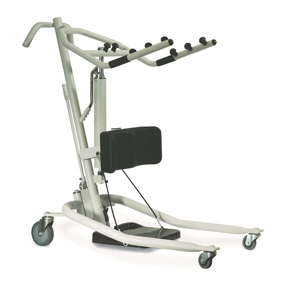
D. As the lift arms are raised, the patient should move legs to the side of the bed until a sitting position on the side of the bed is assumed. NOTE: The caregivers should assist as needed. E. Pull the lift away as needed to accommodate the patient’s feet and legs over the side of the bed. 5. With one caregiver on each side of the patient, place a gait belt on the patient. 6. Ensure that the patient is wearing shoes with skid‐proof soles. 7. If the patient is on the bed, raise the bed (if possible) while ensuring that the patient’s feet remain on the floor. 8. If a walker is to be used, place the walker in front of the patient. 9. Advance the lift toward the patient so that the patient can easily reach the lift arms. 10. Instruct the patient to grasp the lift arms. 11. Ensure that the patient’s feet are directly under them. 12. Begin raising the lift arms. 13. On a count of three, instruct the patient to pull and stand‐up while the caregivers support with the gait belt. ™ Get-U-Up Lift Part No. 1148115 Download from Www.Somanuals.com. All Manuals Search And Download. - Page 25 DO NOT lift the patient. 14. Remove the lift to allow the patient to walk. Lift Arm Lift Arm Mast Post Kneepad Footplate Adjustment Pins Base Note: The upper adjustment pins are typically used for shorter individuals. The lower adjustment pins are typically used for taller individuals. FIGURE 6.1 Standing Procedure ™ Part No. 1148115 Get-U-Up Lift Download from Www.Somanuals.com. All Manuals Search And Download.
-
Page 26: Section 7- Troubleshooting
Lift arms will not lower in upper- Lift arms require a minimum Pull down slightly on the lift arms. most position. weight load to lower from the uppermost position. NOTE: If problems are not remedied by the suggested means, please contact your dealer or Invacare. ™ Get-U-Up Lift Part No. 1148115 Download from Www.Somanuals.com. All Manuals Search And Download. -
Page 27: Section 8- Maintenance
Inspect sling material for wear. Inspect straps for wear. Check that all labels are present and legible. Replace if necessary. ™ Part No. 1148115 Get-U-Up Lift Download from Www.Somanuals.com. All Manuals Search And Download. -
Page 28: Hydraulic Pump
MUST be returned to the factory for repair. DO NOT attempt to open the hydraulic pump or obtain local service. This will void the warranty and might result in damage and costly repair. Consult your dealer or contact Invacare for information. -
Page 29: Detecting Wear And Damage
2. Remove the existing knee pad from the lift. 3. Position the mounting holes in the new knee pad with the mounting holes in the lift. 4. Using the existing hardware, secure the new knee pad to the lift. Button Screw and Knee Pad Washer (1 of 4) Adjustment Pin (1 of 2) FIGURE 8.2 Replacing the Knee Pad ™ Part No. 1148115 Get-U-Up Lift Download from Www.Somanuals.com. All Manuals Search And Download. - Page 30 MAINTENANCE NOTES ™ Get-U-Up Lift Part No. 1148115 Download from Www.Somanuals.com. All Manuals Search And Download.
- Page 31 MAINTENANCE NOTES ™ Part No. 1148115 Get-U-Up Lift Download from Www.Somanuals.com. All Manuals Search And Download.
-
Page 32: Limited Warranty
For warranty service, please contact the dealer from whom you purchased your Invacare product. In the event you do not receive satisfactory warranty service, please write directly to Invacare at the address on the back cover, provide dealer’s name, address, date of purchase, indicate nature of the defect. - Page 33 Free Manuals Download Website h p://myh66.com h p://usermanuals.us h p://www.somanuals.com h p://www.4manuals.cc h p://www.manual-lib.com h p://www.404manual.com h p://www.luxmanual.com h p://aubethermostatmanual.com Golf course search by state h p://golfingnear.com Email search by domain h p://emailbydomain.com Auto manuals search h p://auto.somanuals.com TV manuals search h p://tv.somanuals.com...
Need help?
Do you have a question about the Get-U-Up and is the answer not in the manual?
Questions and answers