Table of Contents

Related Manuals for HST EPS Series


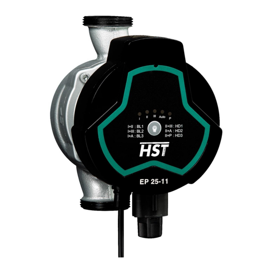
Summary of Contents for HST EPS Series
- Page 1 Installation and Operating Instruction EPS Series Energy-saving Pipeline Canned Motor Pump with speed control via PWM signal for heating and solar systems Heiz- und Sanitärtechnik GmbH Ziegeleistraße 1 5020 Salzburg / AUSTRIA...
-
Page 2: Table Of Contents
Inhaltsverzeichnis 1 NOTES: ........................... 4 2 SIGNS ............................. 5 3 GENERAL ..........................8 3.1 HST EPS ... -11 SERIES CIRCULATION MOTOR PUMP IS MAINLY USED IN DOMESTIC HEATING SOLAR AND HOT ..........................8 WATER SYSTEM 3.2 A .......................... 8 DVANTAGES OVERVIEW ........................... - Page 3 13 PERFORMANCE CURVE ......................25 13.1 G ..................... 25 UIDE ON ERFORMANCE URVE 13.2 C ......................25 URVE CONDITIONS 13.3 P HST EPS…-11 ................26 ERFORMANCE URVE SERIES 14 FEATURES ........................... 28 14.1 N ....................28 AMEPLATE NSTRUCTIONS 14.2 M ......................
-
Page 4: Notes
1 Notes: 01. Read the installation manual carefully before installation and use. 02. The manufacturer will not be liable for any personal injury, pump damage and other property damage due to failure to comply with contents specified in safety warning signs. -
Page 5: Signs
19. If trouble cannot be addressed according to the manual, please close the valves the inlet and outlet of the pump immediately, cut off power supply and contact your ven- dor or service center immediately. 20. This product shall be put in a place out of reach of children. After installation, take an isolation measure to avoid access of children. - Page 7 Installation- Manual & technical Overview →...
-
Page 8: General
3 General 3.1 HST EPS ... -11 series circulation motor pump is mainly used in domestic heating, solar and hot water system. The Production is most applicable to the following systems: • Stable and variable-flow heat supply system • Variable-temperature pipeline heat supply system •... -
Page 9: Overview
OVERVIEW TECHNICAL DATA AND DIMENSIONS more detailed information and graphics from page 23 dimensions material dimension Model Cast Stainless Copper steel iron ◙ EPS25-11 132 132 170 1½” ◙ EPS32-11 132 132 170 2” technical data max. head max. flow power consumption (W) HSTEPS 25-11 180 5,5 m... -
Page 10: Operating Conditions
4 Operating Conditions 4.1 Ambient Temperature Ambient temperature: 0 ℃~ +40 ℃ 4.2 Relative humidity (RH): Max. humidity: 95% 4.3 Medium (liquid delivery) temperature Liquid delivery temperature: +2 ℃~ +110 ℃ To avoid condensation in control box and the stator, the temperature of liquid pumped by the motor pump must be always higher than ambient temperature. -
Page 11: Installation
Warning When the pump is running, the surface temperature of the control panel is high. When switching gears, attention should be pail to preventing scald. 5 Installation Installation • When installing EPS … -11 series circulating pump, the arrow on motor pump case indicates the flow direction of liquid through the pump. -
Page 12: Osition Of Unction Ox
5.2 Position of Junction Box 5.3 Changing Position of Junction Box The junction box can be rotated in a step of 90° The procedure for changing the position of junction box are as follows: 1. Close the valves at the inlet and outlet and release the pressure; 2. -
Page 13: Thermal Insulation Of Motor Pump Body
Warning Pumping liquid may be high-temperature high-pressure; therefore the liquid in the system must be completely drained or the valves on both sides of motor pump must be closed before removing the socket head screws When changing the position of junction box, the motor pump can be started only after the system is filled with pumping liquid or the valves Caution on both sides of motor pump are opened. -
Page 14: Electrical Connection
6 Electrical Connection... - Page 15 Electrical connection and protection shall comply with local codes and norms. Warning The motor pump must be earthed The motor pump must be connected to an external power switch, and the minimum space between all the electrodes is 3mm • EP... -11 series circulating motor pump needs no protection from external mo- tor.
-
Page 16: Control Panel
Speed 1 & 3 flashing Under-power Speed 1 & 5 flashing Over-temperature 7.3 Indication Lamp Area of Motor Pump Setting HST EPS ...-11 series circulation pumps have 11 kinds of settings, pressing the button to choose. 5 different light area indicating all the settings;... -
Page 17: Button For Selecting Motor Pump Settings
7.4 Button for selecting motor pump settings 8 Motor Pump Setting 8.1 Motor Pump Setting Based on System Type... -
Page 18: Control Of Motor Pump
AUTO (Automatically Adaptive Mode) mode setting for at least one week. • If you select to change back to AUTO (Self Adaptive Mode) mode, the HST EPS ...-11 series motor pump can memorize its last setting in AUTO mode and con- tinue adjusting the performance automatically. -
Page 19: Pwm Signal Control Mode
9 PWM Signal Control Mode 9.1 Control and Signal 1) Control Principle HSTEPS…-11 series model pump is controlled by modulated LV PWM (Pulse Width Modulation) digital signal, which means that the variance of velocity de- pends on the external input signal. The variance of velocity is one of the func- tions of input control. -
Page 20: Pwm Input Signal
9.3 PWM Input Signal • In area of high duty-cycle PWM signal, when the input signal fluctuates in the critical point, there will be a delay area to prevent frequent stop and start of the pump. • In area of low duty-cycle PWM signal, the pump runs at high velocity for the sake of system safety. -
Page 21: Pwm Feedback Signal
9.4 PWM Feedback Signal PWM feedback signal can provide operation status of the pump, such as power loss or all kinds of alarm/warning modes. PWM feedback signal will feed back exclusive alarming information. If the power volt- age detects under voltage signal values, its output signal will be set to 75%. Provided sundries settlement exists in the hydraulic system and causes rotor being blocked, the duty cycle of output signal is set to 90%, the alarm will be given higher priority. -
Page 22: Bypass Valve System Installed Between The Inlet Pipeline And Return Pipeline
10 Bypass valve system installed between the Inlet pipeline and return pipeline 10.1 Purposes of bypass valve Bypass valve The purpose of bypass valve: when all the valves and/or temperaturesensing valves of heat from boiler can be distributed. Elements in the system: •... -
Page 23: Manually-Operated Bypass Valve
10.2 Manually-operated Bypass Valve In accordance with the following procedures 1. Adjust the by-pass valve, pump should be set on HS1 (Constant speed I) The minimum flow rate (Qmin) of the system shall be always guaranteed. Please refer to bypass valve manual provided by the manufacturer. 2. -
Page 24: Vent The Heating System
11.3 Vent the heating system 12 Motor Pump Setting and Performance 12.1 Relations between Motor Pump Setting and Performance Note: The red curve stands for constant speed gear (from 1 to 3), the shadow area of blue one is automatic gear, the green one is ratio gear (from 1 to 3), and the yellow one is constant pressure gear (from 1 to 3) -
Page 25: Performance Curve
The input power curve (P1 curve) belongs to every Q/H curve. Power curve represents the power consumption of motor pump in given Q/H curve with Watt as the unit. 13.2 Curve conditions The followings are applicable to the performance curve specified in the HST EPS …-11 series manual: • Test liquid: air-free water. -
Page 26: Performance Curve Hst Eps...-11 Series
13.3 Performance Curve HST EPS…-11 series • Constant speed & AUTO mode performance curve HSTEPS…-11 series Performance Chart(Constant Speed+AUTO Mode) • Constant pressure mode performance curve HSTEPS…-11 series Performance Chart(Constant Pressure) - Page 27 • Proportional pressure performance curve HSTEPS…-11 series Performance Chart (BL Mode) PWM mode performance curve • HSTEPS…-11 series Performance Chart (PWM)
-
Page 28: Features
14 Features 14.1 Nameplate Instructions No. Descriptions Manufacturer Name Voltage (V) Product Model Frequency (Hz) Temperature class Degree of protection Authentication mark Insulation class Energy Index Power Minimum. mode minimum input power P1 Watt Maximum mode maximum input power P2 Cur- Min. -
Page 29: Technical Parameters And Installation Dimensions
15 Technical Parameters and Installation Dimensions 15.1 Technical Parameters Power Supply Voltage 1x(220~240V) V,50/60Hz Energy-efficiency-index EEI≤0.23 Motor Protection The pump needs no external protection Degree of Protection IP44 Insulation Class Relative Humidity Max 95% System Load Bearing 1.0 MPa Suction Port Pressure Liquid Temperature Minimum Inlet Pressure ≤+85℃... -
Page 30: Installation Dimensions
15.2 Installation Dimensions Material Dimension Power Model Stainless Cast iron Copper steel ◙ EPS25-11 132 132 170 11/2” ◙ EPS32-11 132 132 170 2” Startwatt (W) Power input Voltage Current Model (at start) 220~240V EPS 25-11 50/60Hz 220~240V EPS 32-11 50/60Hz... -
Page 31: Trouble-Shooting Schedule
16 Trouble-Shooting Schedule Warning Before conducting any maintenance and repair of the motor pump, ensure that power supply has been cut off and will not be connected accidentally. Symptom Control Panel Cause Corrective Action Equipment fuse burned Replace the fuse The circuit breaker of current Indication control or voltage control... - Page 32 Within warranty period, the product repair is guaranteed by purchase invoice and war- ranty bill. Please send or return the product in need of repair to the local dealer of HST Heiz- und Sanitärtechnik GmbH. or designated maintenance point for repair. HST Heiz- und Sanitärtechnik.
Need help?
Do you have a question about the EPS Series and is the answer not in the manual?
Questions and answers