
Related Manuals for HST EPS Series


Summary of Contents for HST EPS Series
- Page 1 Installation and Operating Instruction EPS Series Energy-saving Pipeline Canned Motor Pump with speed control via PWM signal for heating and solar systems Heiz- und Sanitärtechnik GmbH Ziegeleistraße 1 5020 Salzburg / AUSTRIA...
- Page 2 TABLE OF- CONTENTS...
-
Page 3: Table Of Contents
Table of Contents Installation dimensions & technical data ................5 1. Overview ........................8 2. Service conditions ......................9 3. Installation ......................... 10 4. Electrical connection ....................13 5. Control panel ......................14 6. Setting of electric pump ..................... 15 7. - Page 4 DIMENSIONS & TECHNICAL DATA...
-
Page 5: Installation Dimensions & Technical Data
INSTALLATION DIMENSIONS & TECHNICAL DATA Size (mm) Model Connection HSTEPS 25-4 180 1½” 1” HSTEPS 25-6 180 1½” 1” HSTEPS 25-7.5 180 1½” 1” HSTEPS 32-4 180 2” 1¼” HSTEPS 32-6 180 2” 1¼” HSTEPS 32-7.5 180 2” 1¼” HSTEPS 20-6 130 1”... - Page 6 Precautions for use of EP Series products: The installation manual should be read carefully before installation and use. Any failure to comply with the content marked by safety warning marks may cause personal injury, pump damage and other property loss, for which, the manufacturer shall not assume any responsibility and compensation.
- Page 7 18. If the pump failure can not be cleared in accordance with the description in the instructions, immediately turn off the valve on the pump inlet end and cut off the pump power, besides, immediately contact your local dealer or service center. 19.
-
Page 8: Overview
1. OVERVIEW EPS series circulating pump is mainly used for the water circulation in homeheating and domestic hot water system. EPS series circulating pump is most suitable for the following system: Stable heating system with variable flow Heating system with variable pipeline temperature... -
Page 9: Service Conditions
2. SERVICE CONDITIONS Ambient temperature The ambient temperature is 0℃~+70℃. Relative humidity of the air (RH) The maximum humidity is 95%. Media (conveying liquid) temperature Temperature of liquid conveying +2℃~110℃.To prevent the control box and stator from appearing condensate water, the temperature of pump conveying liquid must be always higher than the ambient temperature. -
Page 10: Installation
3. INSTALLATION Installation 1. Install EPS series circulating pump, arrows on the pump housing indicate the direction of liquid flowing through the pump body. 2. When the pump is installed on the pipeline, its inlet and outlet must be installed with two leather packings provided. - Page 11 3.3 Change to the position of junction box The junction box can rotate in 90°To change the position of junction box, follow the operating steps below: Switch the valves of inlet and outlet and conduct decompression; Loosen and remove the four socket head cap screws that fix the pump body; Rotate the motor to the desired position and match the four screw holes;...
- Page 12 3.4 Thermal insulation of electric pump body Restrict the thermal losses of electric pump body and pipeline. Note Conduct thermal insulation for electric pump body and pipeline so as to reduce the thermal losses of pump and pipeline. Caution Isolating or covering junction box and control panel is not allowed.
-
Page 13: Electrical Connection
The pump must be connected with an external power switch or heating control; the minimum gap between all the electrodes is 3 mm. EPS series circulating pump does not need external motor protection. Check whether the voltage of power supply and frequency match with the parameters marked by pump nameplate. -
Page 14: Control Panel
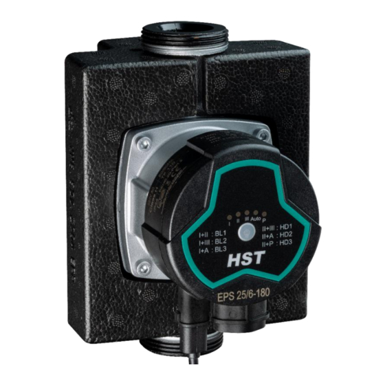
5. CONTROL PANEL Components on the control panel Explanation The pump I, II, III gear display The pump automatic gearshift display (Auto) The pump PWM gear display The pump gear shifting button Special Note 1. If I and II display at the same time, means BL1. If I and III display at the same time, means BL2. -
Page 15: Setting Of Electric Pump
Light area displaying the settings of electric pump EP series circulating pump has 9 kinds of settings, which can be selected by buttons. The setting of electric pump is indicated by the light lit of 9 locations: Key position Number of times of key Fixed light area Explanation AUTO... - Page 16 AUTO (autoadaptation) mode for at least a week before changing the settings of pump. 2. If you choose to change back to AUTO (autoadaptation) mode, EPS series pump can remember the set points of its previous AUTO mode and continue to adjust the performance automatically.
-
Page 17: Pwm Signal Control Mode
7.1 Control and Signal 1) Control Principle HST EPS series model pump is controlled by modulated LV PWM (Pulse Width Modulation) digital signal, which means that the variance of velocity depends on the external input signal. The variance of velocity is one of the functions of input control. - Page 18 7.3 PWM Input Signal • In area of high duty-cycle PWM signal, when the input signal fluctuates in the critical point, there will be a delay area to prevent frequent stop and start of the pump. • In area of low duty-cycle PWM signal, the pump runs at high velocity for the sake of system safety.
- Page 19 7.4 PWM Feedback Signal PWM feedback signal can provide operation status of the pump, such as power loss or all kinds of alarm/warning modes. PWM feedback signal will feed back exclusive alarming information. If the power voltage detects under voltage signal values, its output signal will be set to 75%. Provided sundries settlement exists in the hydraulic system and causes rotor being blocked, the duty cycle of output signal is set to 90%, the alarm will be given higher priority.
-
Page 20: Bypass Valve System (Fitted Between Inlet Pipeline And Return Pipeline)
8. BYPASS VALVE SYSTEM (FITTED BETWEEN INLET PIPELINE AND RETURN PIPELINE) 8.1 Use of bypass valve Bypass valve The role of bypass valve is: when all the valves in the floor heating circuit or the temperature control valve of radiator are closed, it can be ensured that the heat from the boiler will be assigned. -
Page 21: Startup
Gas in the electric pump may cause noise. The noise will disappear after putting it into operation for a few minutes. Set the EPS series electric pump to be HS3 mode in a short time according to the size and structure of system, then gas in the pump will be vented quickly. -
Page 22: Settings And Performance Of Pump
10. SETTINGS AND PERFORMANCE OF PUMP 10.1 Relationship between pump settings and its performance Water pump Settings Function characteristic curve “Autoadaptation” function will automatically control the water pump performance within the specified range. Highest to lowest 1. Adjust the performance of water pump according to the size of system; AUTO (factory proportional pressure 2. -
Page 23: Performance Curve
Q/H curve. 11.2 Curve conditions The following description applies to the performance curves in EPS series manual: Testing liquid: gas-free water. Applicable density of curve ρ = 983.2 kg/cubic meter, and the liquid temperature is +60 ℃. All the values expressed by curves are averages, they can not be taken as the guaranteed curves. - Page 24 EPS XX-5 series Performance curve EPS XX-6 series Performance curve...
- Page 25 EPS XX-7 Serie EPS XX-7.5 Serie...
-
Page 26: Characteristics
12. CHARACTERISTICS 12.1 Description of nameplate Explanation Maximum mode maximum current Power Minimum mode minimum current Maximum mode maximum current current Minimum mode minimum current Maximum pressure-bearing of system (MPa) Product No. Motor steering Voltage (V) Insulation class Protection Level Certification mark Frequency (Hz) Temperature grade... -
Page 27: Technical Data And Installation Dimension
12.2 Model explanation Pump model is consisted of upper Latin letters and Arabic numerals etc., whose meanings are as follows: 13. TECHNICAL DATA AND INSTALLATION DIMENSION 11.1 Technical data Supply voltage 220~240V, 50/60Hz Energy efficiency index EEI≤0.20 Motor protection Pump does not need external protection Protection Level IP44 Insulation class... -
Page 28: Startwatt - Power Input - Model - Voltage - Current
Temperature grade TF110 Surface temperature Maximum surface temperature should not exceed +125℃ Liquid temperature 2~+110℃ To prevent the control box and stator from appearing condensate water, the temperature of pump conveying liquid must be always higher than the ambient temperature Liquid temperature Ambient temperature (℃) - Page 29 FAULTCHECKLIST...
-
Page 30: Fault Checklist
14. FAULT CHECKLIST Warning: Before carrying out any maintenance and repair to the electric pump, make sure the power is disconnected and will not be accidentally switched on. Control Panel Corrective Action Symptom Cause Equipment fuse burned Replace the fuse The circuit breaker of current control or voltage Indication lamp Connect the circuit breaker... - Page 32 Within warranty period, the product repair is guaranteed by purchase invoice and warranty bill. Please send or return the product in need of repair to the local dealer of HST Heiz- und Sanitärtechnik GmbH. or designated maintenance point for repair. HST Heiz- und Sanitärtechnik.
Need help?
Do you have a question about the EPS Series and is the answer not in the manual?
Questions and answers