Table of Contents
Advertisement
Quick Links
Advertisement
Table of Contents

Related Manuals for Buchi I-180


Summary of Contents for Buchi I-180
- Page 1 Operation Manual Interface I-180...
- Page 2 CH-9230 Flawil 1 E-Mail: quality@buchi.com BUCHI reserves the right to make changes to the manual as deemed necessary in the light of experience, especially with respect to structure, illustrations and technical details. This manual is copyrighted. Information from it may neither be reproduced, distributed, or used for competitive purposes, nor made available to third parties.
-
Page 3: Table Of Contents
5.1.1 Installing on the Rotavapor®.................... 15 5.1.2 Installing on the vacuum pump .................... 16 5.1.3 Installing on a laboratory stand .................... 17 Connecting the BUCHI communication cable.................. 17 Connecting vacuum ........................... 18 5.3.1 Connecting the vacuum pump ..................... 18 5.3.2 Connecting the valve unit..................... 18... - Page 4 Taking out of service and disposal.................... 31 Taking out of service.......................... 31 Disposal ............................. 31 Returning the instrument ........................ 31 Appendix ............................ 32 10.1 Spare parts and accessories ...................... 32 10.1.1 Spare parts .......................... 32 10.1.2 Wear parts ........................... 32 10.1.3 Accessories.......................... 33 Operation Manual Interface I-180...
-
Page 5: About This Document
1.3 Connected instruments In addition to this operation manual, follow the instructions and specifications in the documentation for the connected instruments. Operation Manual Interface I-180 5/36... -
Page 6: Safety
— The staff must comply with the local applicable requirements and regulations for safe and hazard-conscious working practices. — Safety-related incidents that occur while using the instrument should be reported to the manufacturer (quality@buchi.com). 6/36 Operation Manual Interface I-180... -
Page 7: Personal Protective Equipment
BÜCHI Labortechnik AG Safety | 2 BUCHI service technicians Service technicians authorized by BUCHI have attended special training courses and are authorized by BÜCHI Labortechnik AG to carry out special servicing and repair measures. 2.4 Personal protective equipment Depending on the application, hazards due to heat and/or corrosive chemicals may arise. - Page 8 2 | Safety BÜCHI Labortechnik AG Only allow changes to be made by BUCHI service technicians. BUCHI accepts no liability for damage, faults and malfunctions resulting from unauthorized modifications. 8/36 Operation Manual Interface I-180...
-
Page 9: Product Description
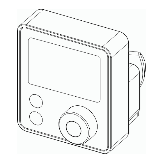
Regulate to a set pressure — Regulate the vacuum pump speed — Start/Stop the vacuum pump — Regulate a set pressure for a set time period 3.2 Configuration 3.2.1 Front view Interface cover Display STOP Button Button Navigation control Operation Manual Interface I-180 9/36... -
Page 10: Rear View
3 | Product description BÜCHI Labortechnik AG 3.2.2 Rear view Interface back cover Type plate Mounting fixture Plug 3.2.3 Connections VALVE Valve unit Communication Vacuum Inert gas 10/36 Operation Manual Interface I-180... -
Page 11: Display Layout
Error occurrence Hysteresis (mbar/hPa/torr) Leak rate (mbar/hPa/torr / min Operating mode Pump continuously Vacuum control with set pressure Maximum pump speed System venting active Hold vacuum control Pump ON One point calibration value Set value Operation Manual Interface I-180 11/36... -
Page 12: Scope Of Delivery
Regulation range Ambient – 0 mbar Measurement accuracy ± 2 mbar (after calibration at constant temperature) Vacuum connection GL14 IP Code IP44 Minimum clearance on all sides none Controller 3" Dark segment display Certificate CB, CE, UL/CSA 12/36 Operation Manual Interface I-180... -
Page 13: Ambient Conditions
The installation site meets the requirements for the connected devices. See related documentation. — The installation site is in a well ventilated area. — The instrument is required to be installed on a Rotavapor®, vacuum pump or a laboratory stand. Operation Manual Interface I-180 13/36... -
Page 14: Transport And Storage
Wherever possible, store the instrument in its original packaging. After storage, check the instrument, all seals and tubing for damage and replace if necessary. 4.3 Lifting the instrument Lift the instrument at the points indicated. 14/36 Operation Manual Interface I-180... -
Page 15: Installation
Installation | 5 5 Installation 5.1 Installing the interface The interface is designed to be mounted on BUCHI instruments or a laboratory stand. 5.1.1 Installing on the Rotavapor® NOTE The interface is designed to be mounted on a Rotavapor® R-80. -
Page 16: Installing On The Vacuum Pump
5.1.2 Installing on the vacuum pump NOTE The interface is designed to be mounted on a Vacuum Pump V-80 or Vacuum Pump V-180. Position the interface holder. Vacuum Pump V-180 Vacuum Pump V-80 Tighten the knurled-head screw. 16/36 Operation Manual Interface I-180... -
Page 17: Installing On A Laboratory Stand
Connect the instrument. See additional chapter according to the delivered components. 5.2 Connecting the BUCHI communication cable Precondition: The Interface I-80 / I-180 is installed. Plug the communication cable into the interface. Connect the communication cable to the Rotavapor® or the vacuum pump. -
Page 18: Connecting Vacuum
The valve unit is only used if a central vacuum system is used. Precondition: Recommended hose lengths: The Woulff bottle with valve unit is installed. 400 mm (Condenser to Woulff bottle) The Interface I-180 is installed. 700 mm Cut the hose to needed lengths. (Interface to Woulff bottle) 900 mm (Vacuum system to Woulff bottle) Install the vacuum hose onto the hose nipples. - Page 19 PUMP PUMP Attach the hose to the Woulff bottle connection CONTR CONTR Attach the hose to the interface. Plug the valve unit cable into the interface VALVE VALVE connection Clamp the cable through the fixture. Operation Manual Interface I-180 19/36...
-
Page 20: Operation
Activates the function. 6.1.2 Changing the set pressure Turn the navigation control. ð Changes the symbol or value. 6.1.3 Stop the vacuum control Touch the STOP button. ð Stops the vacuum control and fully aerates the system. 20/36 Operation Manual Interface I-180... -
Page 21: Aerating The System
6.2 Main functions in cont mode 6.2.1 Starts or holds the vacuum pump Push the navigation control. ð Activates the function. 6.2.2 Control the vacuum pump speed Turn the navigation control. ð Changes the symbol or value. Operation Manual Interface I-180 21/36... -
Page 22: Stop The Vacuum Pump
6.3 Settings 6.3.1 Setting the pressure p set This setting is only possible in the mode. Navigation path ➔ ➔ Set pressure Touch the SET button. ð Settings symbol appears. ð Blinking value is active. 22/36 Operation Manual Interface I-180... -
Page 23: Setting The Pump Speed
This setting is only possible in the mode. Navigation path ➔ ➔ Set pump speed Touch the SET button. ð Settings symbol appears. ð Blinking value is active. Turn the navigation control. ð Changes the value. Operation Manual Interface I-180 23/36... -
Page 24: Setting To Default Settings
Setting the maximum pump speed limit in operation. Leak test Setting to perform an automatic leak test. Pressure unit mbar Changing the pressure unit. torr Pressure calibration Setting an offset for the pressure calibration. Adjust 24/36 Operation Manual Interface I-180... -
Page 25: Advanced Settings With Valve Unit
Vacuum pump stops and system aerates when timer is finished. Leak test Setting to perform an automatic leak test. Pressure unit Changing the pressure unit. mbar torr Pressure calibration Adjust Setting an offset for the pressure calibration. Operation Manual Interface I-180 25/36... - Page 26 Touch the SET button and the navigation control. ð Settings symbol appears. ð Blinking symbol or value is active. Turn the navigation control. ð Changes the symbol or value. Touch the SET button to navigate through the settings. 26/36 Operation Manual Interface I-180...
-
Page 27: Cleaning And Servicing
Do not carry out any servicing and cleaning operations that involve opening the housing. Use only genuine BUCHI spare parts in order to ensure correct operation and preserve the warranty. Carry out the service and cleaning operations described in this section to extend the lifetime of the instrument. - Page 28 7 | Cleaning and servicing BÜCHI Labortechnik AG Wait until the timer finishes. ð Leak rate appears. Δp = mbar/min Δp = Torr/min Δp = hPa/min 28/36 Operation Manual Interface I-180...
-
Page 29: Help With Faults
Pressure sensor defective Contact BUCHI Customer Service. Initialization error Contact BUCHI Customer Service. Valve unit driver error Contact BUCHI Customer Service. Error codes from connected BUCHI Vacuum Pump Error code Description Action Fill level sensor removed Check the sensor connection. during operation... -
Page 30: Customer Service
BUCHI. The customer service and support offers the following support: — Spare part delivery — Repairs — Technical advice Addresses of official BUCHI customer service offices can be found on the BUCHI website. www.buchi.com 30/36 Operation Manual Interface I-180... -
Page 31: Taking Out Of Service And Disposal
When disposing, observe the disposal regulations of the materials used. For the used materials see Chapter 3.5 "Technical data", page 12 or the material labeling on the parts. 9.3 Returning the instrument Before returning the instrument, contact the BÜCHI Labortechnik AG Service Department. https://www.buchi.com/contact Operation Manual Interface I-180 31/36... -
Page 32: Appendix
BÜCHI Labortechnik AG 10 Appendix 10.1 Spare parts and accessories Use only genuine BUCHI consumables and spare parts in order to ensure correct, safe and reliable operation of the system. NOTE Any modifications of spare parts or assemblies are only allowed with the prior written permission of BUCHI. -
Page 33: Accessories
Non-return valve and condensate trap Interface holder 11075588 To install the Interface I-80 / I-180 on the Vacuum pump V-80 / V-180 Stand. V stand with rod, 600 mm 048891 Used as a holder for interface when it cannot be mounted on an instrument. - Page 34 Tubing, synthetic rubber, Ø6/13 mm, black, per m 11063244 Use: Vacuum Communication cable Order no. Image Communication cable. BUCHI COM, 0.3 m, 6p 11058705 Communication cable. BUCHI COM, 0.9 m, 6p 11070540 Communication cable. BUCHI COM, 1.8 m, 6p 11058707 Communication cable. BUCHI COM, 5.0 m, 6p 11058708 Communication cable.
- Page 36 11594509 | A en We are represented by more than 100 distribution partners worldwide. Find your local representative at: www.buchi.com...
Need help?
Do you have a question about the I-180 and is the answer not in the manual?
Questions and answers