Table of Contents
Advertisement
Quick Links
Advertisement
Table of Contents

Related Manuals for Buchi I-300


Summary of Contents for Buchi I-300
- Page 1 Interface I-300 Operation Manual...
- Page 2 CH-9230 Flawil 1 E-Mail: quality@buchi.com BUCHI reserves the right to make changes to the manual as deemed necessary in the light of experience, especially with respect to structure, illustrations and technical details. This manual is copyrighted. Information from it may neither be reproduced, distributed, or used for competitive purposes, nor made available to third parties.
-
Page 3: Table Of Contents
Symbols on the status bar .................. 22 Scope of delivery ......................... 23 Technical data ........................ 23 3.6.1 Interface........................ 23 3.6.2 Junction boxes...................... 23 3.6.3 Ambient conditions .................... 24 3.6.4 Materials ......................... 24 Transport and storage ...................... 25 Transport .......................... 25 Storage .......................... 25 Operation Manual Interface I-300... - Page 4 Overview: setting up vacuum tubing connections .......... 34 Connecting AutoDest sensor to vapor temperature sensor (optional accessory) .... 36 Connecting foam sensor (optional accessory) .............. 37 Connecting valve unit for external vacuum................ 39 Operating I-300 and I-300 Pro in parallel ................ 39 Operation.......................... 40 Navigating the menu...................... 40 6.1.1 Selecting menu items .....................
- Page 5 10.5.3 Error data........................ 79 10.5.4 Maintenance data .................... 79 10.5.5 System configuration data .................. 79 10.5.6 Data storage period .................... 79 10.5.7 Device settings ....................... 80 10.5.8 Contact data ...................... 80 10.5.9 Location data ...................... 80 Operation Manual Interface I-300...
-
Page 6: About This Document
The following symbols are displayed in this operation manual or on the device: 1.2.1 Warning symbols Symbol Meaning Symbol Meaning General warning Corrosive substance Dangerous electrical voltage Flammable substance Biological hazard Potentially explosive atmos- phere Breakable items Dangerous gases Hot surface Health-harming or irritant substances 6/82 Operation Manual Interface I-300... -
Page 7: Mark-Ups And Symbols
Signal Signals are marked-up like this. Trademarks Product names and registered or unregistered trademarks that are used in this document are used only for identification and remain the property of the owner in each case. Operation Manual Interface I-300 7/82... -
Page 8: Safety
Safety Intended use The [Interface I-300] is intended for indicating vacuum within an operating range of 0 mbar to ambient atmospheric pressure. The measurement and regulation of the vacuum is performed by means of a VacuBox. The [Interface I-300] has been... -
Page 9: Residual Risks
— Safety-related incidents that occur while using the device should be reported to the manufacturer (quality@buchi.com). BUCHI service technicians Service technicians authorized by BUCHI have attended special training courses and are authorized by BÜCHI Labortechnik AG to carry out special servicing and repair measures. - Page 10 Büchi Labortechnik AG 2 | Safety BUCHI accepts no liability whatsoever for damage arising as a result of unauthorized modifications. 10/82 Operation Manual Interface I-300...
-
Page 11: Product Description
Product description | 3 Product description Description of function The [Interface I-300] is designed for indicating, adjusting and controlling the complete distillation system. The Interface I-300 settings enable precise specification of the individual process parameters.For example: — Rotation speed of the evaporating flask —... -
Page 12: Configuration
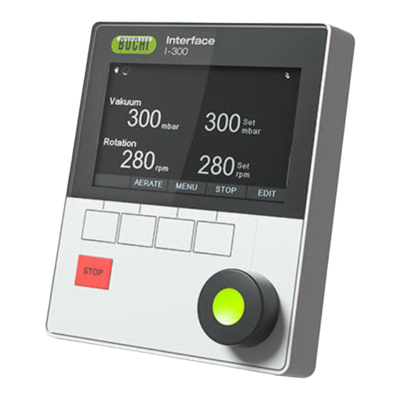
Büchi Labortechnik AG 3 | Product description Configuration 3.3.1 Front view Fig. 1: Front view of Interface I-300 Display Navigation control STOP button (emergency stop) Function buttons 3.3.2 Rear view Fig. 2: Rear view of Interface I-300 LAN port Locating lug for bracket... -
Page 13: Vacubox (Connections)
Product description | 3 3.3.3 VacuBox (connections) Other BUCHI laboratory equipment is connected to the [Interface I-300] in series together with the VacuBox. The individual devices are connected to one another via the standard BUCHI communication port (7). See Chapter 5.2.3 "Overview: Setting up communication connections (COM)", page 33. -
Page 14: Legacybox (Connections)
LegacyBox (connections) Connection of a LegacyBox is required whenever legacy BUCHI laboratory equipment is to be controlled via the [Interface I-300]. The LegacyBox is connected to the distillation system using a standard BUCHI communication cable and has other connection options such as an RS-485 communication port. There is also the option of incorporating pumps of other makes in the Rotavapor system and controlling them via the interface. - Page 15 0 – 10 V (max. 20 mA, min. 500 Ohm) Relay In Max. 30 V 2 A, electrically isolated Spare Spare Relay Out Max. 30 V 2 A, electrically isolated Shield Shield, connected to ground Operation Manual Interface I-300 15/82...
-
Page 16: Display (Touch-Screen)
Display (touch-screen) Fig. 6: Display layout Status bar Current setting (e.g. vacuum) Menu bar Scroll bar Current reading (e.g. vacuum) Function activated if navigation con- trol is pressed Functions of the function buttons be- low (context-dependent) 16/82 Operation Manual Interface I-300... -
Page 17: Type Plate
Büchi Labortechnik AG Product description | 3 3.3.6 Type plate The type plate is on the rear of the [Interface I-300]. BÜCHI Labortechnik AG CH-9230 Flawil/Switzerland Type: I-300 1000000000 Volt: 30 VDC Frequ.: Power: 3 W Built: 2014 Made in Switzerland Fig. 7: Type plate (example) -
Page 18: Favorites Menu
— Wearing parts — Startup info 3.4.2 Favorites menu For creating favorites. See Creating favorites 3.4.3 Operating modes menu The Interface I-300 distinguishes between the following operating modes for a distillation system: Operating mode Purpose Content [Manual] Carrying out distilla- See Chapter 6.2.3 "Executing Manual... -
Page 19: Configuration Menu
The [Configuration] menu contains the following submenus: — Maintenance see Maintenance submenu — Settings see Settings submenu — BUCHI Cloud Services see Chapter "BUCHI Cloud Services submenu ", page 21 — System information see System Information submenu Maintenance submenu The submenu [Maintenance] contains the following actions:... - Page 20 Max. pump speed in %: 10 –100 %. ery] [Display brightness] Enter value Display illumination level in %: 0 – 100 %. [eco mode] On/Off and entry of See Chapter 6.4 "Activating eco mode", figures page 58 20/82 Operation Manual Interface I-300...
- Page 21 [Delete APP connec- Confirmation ques- All connections settings entered for the tion] tion instrument are reset. BUCHI Cloud Services submenu The submenu [BUCHI Cloud Services] contains functions and views relating to cloud solutions. Action Option Explanation [System owner] Info Shows the details of the registered sys- tem owner.
-
Page 22: Libraries Menu
Shows the home screen. 3.4.6 Symbols on the status bar Symbol Status Manual distillation Distillation using a method Drying AutoDest distillation Distillation running Continuous pumping The instrument is connected to the BUCHI Cloud. Timed distillation 22/82 Operation Manual Interface I-300... -
Page 23: Scope Of Delivery
Regulating range Ambient pressure - 0 mbar Measuring accuracy ± 2 mbar (after calibra- tion at constant temper- ature) Temperature compensation 0.07 mbar/K 0.07 mbar/K Vacuum connection GL14 Magnetic valve supply 24 V Power consumption Operation Manual Interface I-300 23/82... -
Page 24: Ambient Conditions
50 % at 40 °C The laboratory equipment described in this document may only be used in indoor areas. 3.6.4 Materials Component Material Pressure foil Polyester Casing Vent tube connection Pressure sensor Al₂O₃ 96% 24/82 Operation Manual Interface I-300... -
Page 25: Transport And Storage
Storage Make sure that the ambient conditions are complied with (see Chapter 3.6 "Technical data", page 23). Wherever possible, store the device in its original packaging. After storage, check the device for damage and replace if necessary. Operation Manual Interface I-300 25/82... -
Page 26: Installation
Büchi Labortechnik AG 5 | Installation Installation Fitting the Interface I-300/I-300 Pro The Interface I-300/I-300 Pro can be mounted on one of the following BUCHI laboratory devices: — Rotavapor R-300 — Vacuum Pump V-300 — Rotavapor R-220 Pro Alternatively, the Interface I-300/I-300 Pro can be mounted separately on a laboratory stand, see Chapter 5.1.3 "Mounting interface unit on laboratory stand... - Page 27 Connect the communication cable to the COM port on the rear of the interface unit. Position the interface unit (3) on the holder and fix it in place using the knurled- head screw (1) supplied. When doing so, make sure that the communication cable is not trapped. Operation Manual Interface I-300 27/82...
-
Page 28: Fitting Interface Unit On Vacuum Pump V-300
Rubber plug and threaded hole Tools required: — Torx key Tx30 The [Interface I-300] can be mounted on the top of the Vacuum Pump V-300 using a holder. Remove the rubber plug (4) from the top panel of the vacuum pump. Use a screwdriver if necessary. -
Page 29: Mounting Interface Unit On Laboratory Stand (Optional Accessory)
Interface unit T-screw Laboratory stand The [Interface I-300] can also be mounted on a laboratory stand using a holder. Position the holder (1) on the laboratory stand (3) and fix it in place using the T- screw (5). Position the interface unit (2) on the flat face (1) of the holder and fix it in place using a knurled-head screw (4). -
Page 30: Mounting Interface Unit On A Wall Bracket (Optional Accessory)
Fixing screws for interface unit Lug on front plate The [Interface I-300] can also be mounted directly onto a plastered or tiled wall or a laboratory fume hood with the aid of a wall bracket. Position the rear plate (4) of the two-part wall bracket on the wall. Note: the word "UP"... -
Page 31: Connecting Communication Cables To Interface Unit
The F-3xx is a recirculating chiller with a sealed circulation system. It is available in various capacity ratings. The Interface I-300/I-300 Pro together with the VacuBox can be used to control and monitor the vacuum. It can control the Rotavapor, the Vacuum Pump V-300 and the Recirculating Chiller F-3xx. -
Page 32: Establishing Lan Connection
The following port has to be enabled in the firewall settings on the internet gateway: — TCP (HTTPS) traffics through remote port 443 In order to use the BUCHI Cloud a DNS server must be configured on the instrument. NOTE If there is no DNS server available enter the IP address for the BUCHI Cloud connection manually. -
Page 33: Overview: Setting Up Communication Connections (Com)
(example) 5.2.4 Overview: setting up coolant tubing connections The tubing connections between the various items of BUCHI laboratory equipment form a sealed circulation system. The starting and finishing point is always the recirculating chiller (F-3xx). Below is an example of the tubing connections between the laboratory apparatus. -
Page 34: Overview: Setting Up Vacuum Tubing Connections
5.2.5 Overview: setting up vacuum tubing connections The vacuum tubing connections in a typical BUCHI distillation system lead from the Rotavapor R-300 via a Woulff bottle to the Vacuum Pump V-300/V-600. The vacuum is measured by means of the VacuBox, which is also connected to the Woulff bottle. - Page 35 Woulff bottle marked CONTR (5) and the VacuBox (6). The pressure is measured in the VacuBox. The current working pressure can be indicated and controlled by means of the Interface I-300/I-300 Pro. NOTE The VacuBox and Woulff bottle can be mounted either on the Rotavapor R-300 or the Vacuum Pump V-300/V-600.
-
Page 36: Connecting Autodest Sensor To Vapor Temperature Sensor (Optional Accessory)
Communication connection between Coolant outlet on condenser AutoDest sensor and VacuBox NOTE There are two arrows stamped on the AutoDest sensor indicating the direction of flow for the coolant. The coolant tubing should be connected accordingly. 36/82 Operation Manual Interface I-300... -
Page 37: Connecting Foam Sensor (Optional Accessory)
The communication cable from the foam sensor is connected to the VacuBox, see Chapter 3.3.3 "VacuBox (connections)", page 13. NOTICE Risk of heat damage to electronic components Only use the foam sensor at vapor temperatures up to 85 °C. Operation Manual Interface I-300 37/82... - Page 38 The washer is slid over the glass tube of the foam sensor so that it comes to rest in the area below the drip catcher of the cooling condenser. The tip of the washer should point downwards. 38/82 Operation Manual Interface I-300...
-
Page 39: Connecting Valve Unit For External Vacuum
If a mobile connection (see Chapter 5.2.2 "Establishing LAN connection", page 32) is desired when the I-300 and I-300 Pro are operating in parallel, the LAN cable must only be connected to one of the interface units, preferably the I-300 Pro. -
Page 40: Operation
6 | Operation Operation Navigating the menu The I-300 Pro offers the fundamental option of navigating the menu either by using the function buttons and the navigation control or by means of the touch-screen functionality of the display. The touch-screen functions can be operated using laboratory gloves. Liquids on the screen do not pose a problem either and do not impair functionality in any way. -
Page 41: Entering Parameter Settings
6.1.2 Entering parameter settings The Interface I-300 offers the facility for manually setting various parameters. The parameters are shown on the home screen of the interface unit. Rotating the navigation control selects each parameter in turn. The currently selected parameter is highlighted in green. -
Page 42: Performing Distillation
Fig. 24: Options for the setting Press the navigation control to choose SAVE and save the selected option. Performing distillation The Interface I-300 offers the following operating modes for carrying out distillation: Operating mode [Manual] See Performing manual distillation... -
Page 43: Basic Functions
ð While venting is active, the status bar is shown in yellow on the display. Fig. 25: Home screen during venting To evacuate the system to the specified vacuum again after venting, press the function button HOLD OFF. Operation Manual Interface I-300 43/82... -
Page 44: Executing Manual Mode
CAUTION Risk of personal injury and property damage from unexpected equipment behavior Always carefully check the pre-programmed settings before every distillation process. Navigation path ➔ Operating modes ➔ Manual 44/82 Operation Manual Interface I-300... - Page 45 Starting manual distillation Precondition: R Process parameters have been set. Press the function button START. ð The display shows the home screen in inverse type. ð The status bar shows the symbol for distillation in progress. Operation Manual Interface I-300 45/82...
- Page 46 Fig. 29: Distillation process started ð The actual readings are shown more brightly in the left-hand column of the display. The right-hand column shows the specified settings. To abort the cooling process prematurely, press the function button STOP. 46/82 Operation Manual Interface I-300...
-
Page 47: Executing Timer Mode
In [Timer] mode, a distillation process with a predefined duration is started. CAUTION Risk of personal injury and property damage from unexpected equipment behavior Always carefully check the pre-programmed settings before every distillation process. Navigation path ➔ Operating modes ➔ Timer Operation Manual Interface I-300 47/82... - Page 48 — Actual reading for vapor temperature AutoDest sensor or vapor temperature sensor — Actual reading and specified setting for duration of distillation (timer) Starting timer-controlled distillation Precondition: R Timer and process parameters have been set. Press the function button START. 48/82 Operation Manual Interface I-300...
- Page 49 ð After the parameters have been altered, the timer jumps to the new setting and starts counting down the time from the beginning. The progress bar in the status bar jumps back to the beginning. Edit other parameters as necessary. Operation Manual Interface I-300 49/82...
-
Page 50: Executing Continuous Pumping Mode
Navigate to the menu and select the menu item [Continuous Operating modes pumping], see Chapter 6.1 "Navigating the menu", page 40. ð The display shows the home screen with the symbol for continuous pumping in the status bar. 50/82 Operation Manual Interface I-300... - Page 51 — Actual reading and specified setting for Rotavapor R-300 rotation speed (evaporating flask) — Actual reading and specified setting for Heating Bath B-301/B-305 heating bath temperature — Actual reading and specified setting for Recirculating Chiller F-3xx cooling temperature Operation Manual Interface I-300 51/82...
-
Page 52: Performing Automatic Distillation
Navigate to the "Operating modes" screen and select the menu item "AutoDest", see Chapter 6.1 "Navigating the menu", page 40. ð The display shows the home screen with the symbol for automatic distillation in the status bar. 52/82 Operation Manual Interface I-300... - Page 53 R Process parameters have been set. Press the function button START. ð The display shows the home screen in inverse type. ð The status bar shows the symbol for distillation in progress. Fig. 42: Information displayed during automatic distillation Operation Manual Interface I-300 53/82...
- Page 54 If the specified setting for the pressure is altered manually, the level set automatically is lost and the operating mode switches to manual distillation. NOTE The specified settings for the individual parameters may only be altered gradually as otherwise distillation may be aborted. 54/82 Operation Manual Interface I-300...
-
Page 55: Executing Drying Mode
➔ Operating modes ➔ Drying Fig. 43: Selecting the option [Drying] on the menu Operating modes Navigate to the menu and select the menu item [Drying], see Operating modes Chapter 6.1 "Navigating the menu", page 40. Fig. 44: Home screen showing [Drying] symbol Operation Manual Interface I-300 55/82... -
Page 56: Using The Solvent Library
(timer) Using the solvent library The [Interface I-300] has an internal solvent library. Stored in that library are the most common solvents together with an algorithm in each case. Based on the chemical properties of the solvent, the algorithm calculates and dynamically sets the ideal vacuum according to the current readings for heating bath and coolant temperature. - Page 57 To start a distillation process directly from the solvent library, press the function button START. To apply the settings for the selected solvent and return to the interface unit home screen, press OK. On the home screen, the settings for the individual process parameters can be edited. Operation Manual Interface I-300 57/82...
-
Page 58: Activating Eco Mode
Activating eco mode The [Interface I-300] offers an "eco mode" option for saving energy if the distillation system remains inactive for a predefined period of time. In eco mode, the distillation system shuts down the activity of the heating bath and recirculating chiller after a defined delay period so that: —... -
Page 59: Setting Hysteresis
The hysteresis setting is only relevant if the distillation system is not being operated with a BUCHI Vacuum Pump V-300 but with a different make of pump or with a laboratory vacuum supply, and is controlled by means of a valve. -
Page 60: Activating Come Here Function
All apps connected to the instrument are sent a message. Navigation path ➔ Precondition: R Monitoring services have been installed and set up. For details see "BUCHI Cloud and Monitoring Services Quick Guide" or https://www.buchi.com/en/buchi-cloud Navigate to the screen and select the function button [Come here], see Start Chapter 6.1 "Navigating the menu", page 40. -
Page 61: Cleaning And Servicing
Any servicing and repair work which involves opening up the casing may only be carried out by BUCHI service technicians. Use only genuine BUCHI consumables and spare parts in order to ensure correct operation of the device and preserve the warranty. -
Page 62: Checking Vacuum Seal
When asked to confirm, press [OK]. ð The rotation hours are reset. Fitting GL14 cap nut with tube seal Fig. 55: Fitting GL14 cap nut with tube seal (example shows VacuBox) Tube seal Tubing GL14 cap nut 62/82 Operation Manual Interface I-300... -
Page 63: Checking Seals
➜ Configuration ➜ System information ➜ AutoDest sensor Place the AutoDest sensor in a homogeneous water bath. Navigate to the sub-screen and select the menu item [Au- System information toDest sensor], see Chapter 6.1 "Navigating the menu", page 40. Operation Manual Interface I-300 63/82... -
Page 64: Calibrating The Pressure Sensor
Press the navigation control to choose OK and confirm the calibration offset. Calibrating the pressure sensor The pressure sensor is calibrated at the factory by BUCHI prior to delivery. However, it can be recalibrated with the aid of an external reference pressure gauge at any time. -
Page 65: Offset Calibration
Connect the reference pressure gauge to the same vacuum system that the pump and interface unit are connected to. Navigate to the "Service" screen and select the menu item "Pressure calibration", see Chapter 6.1 "Navigating the menu", page 40. Operation Manual Interface I-300 65/82... -
Page 66: Loading Factory Calibration
ð The device asks you to confirm that the factory calibration should be reloaded. Fig. 59: Menu item "Back to factory calibration" Press the function button OK to confirm or the function button ESC to retain the existing calibration settings. 66/82 Operation Manual Interface I-300... -
Page 67: Help With Faults
The addresses of the official BUCHI Customer Service offices can be found on the BUCHI website at: . If you have any questions regarding technical www.buchi.com... -
Page 68: Esupport
BUCHI technical engineer. Navigation path ➔Configuration ➔BUCHI Cloud Services Precondition: R The BUCHI Cloud Services have been installed and set up. For details see "BUCHI Cloud and Monitoring Services Quick Guide" or https://www.buchi.com/en/buchi- cloud Navigate to the sub-screen, see Chapter 6.1... -
Page 69: Taking Out Of Service And Disposal
Taking out of service and disposal | 9 Taking out of service and disposal Taking out of service Switch off the [Interface I-300] and disconnect it from the mains power supply. Remove all tubing and communication cables from the device. Disposal The operator is responsible for proper disposal of the [Interface]. -
Page 70: Appendix
86.2 0.660 Isopropanol 60.1 0.786 Isopentanol 88.1 0.809 Methylethylketone 72.1 0.805 Methanol 32.0 1227 0.791 Dichlormethane 84.9 1.327 Pentane 72.1 0.626 n-propanol 60.1 0.804 Pentachloroethane 202.3 1.680 1,1,2,2-tetra- 167.9 1.595 chloroethane Tetrachloromethane CCl 153.8 1.594 70/82 Operation Manual Interface I-300... -
Page 71: Spare Parts And Accessories
– 10.2 Spare parts and accessories Use only genuine BUCHI consumables and spare parts in order to ensure correct, safe and reliable operation of the system. NOTE Any modifications of spare parts or assemblies are only allowed with the prior written permission of BUCHI. - Page 72 Meant to be used with the In- terface I-300 / I-300 Pro. Holder. To fix interface on lab stand 11059021 To fix Interface I-300 / I-300 Pro, VacuBox and LegacyBox on lab stand, Rotavapor® R-21x or Vacuum Pump V-7xx. Incl. support, fixing clamp. 72/82...
- Page 73 DIN, 1.5 m Flow valve without flask, meant to be used with a central- ized vacuum source or an unregulated vacuum pump. Meant to be used with the Interface I-300 /I -300 Pro. Valve unit. Incl. Woulff bottle, 125 mL, P+G, 11061887...
-
Page 74: Wearing Parts
Hose, set. Incl. GL14 set, FEP tube 11061756 11065373 Used to connect VacuBox and Valve unit/Woulff bottle when both are fixed on the Rotavapor® R-300. Tubing. FEP, Ø6/8 mm, transparent, 40 mm 11059909 Connection tubing Woulff bottle. 74/82 Operation Manual Interface I-300... -
Page 75: Spare Parts
For Rotavapor® R-300, Heating Bath B-300 Base, Interface I-300/I-300 Pro and Recirculating Chiller F-305/F-308/F-314. VacuBox. Incl. support set 11060914 Communication interface between Rotavapor® R-300 and Interface I-300/I-300 Pro or Vacuum Pump V-300/V-600 and Interface I-300/ I-300 Pro. Support foam sensor, Incl. clamping nut, support 11059024 ring... -
Page 76: Health And Safety
List of hazardous materials that have been in contact with the products: Chemical, material Hazard category 76/82 Operation Manual Interface I-300... -
Page 77: Handling Data
The following communication details relate to Version 1.0 of the interface. Information is subject to amendment in respect of extent and content. NOTE External control of the equipment via the BUCHI Cloud is not implemented. Data transmission via the LAN interface to the server Category... - Page 78 At most 1 year after last use connection) — Status data At least 24 hrs, max. 48 hrs Data that is older than 24 hrs is deleted — Event data after 24 hrs. — Process data 78/82 Operation Manual Interface I-300...
-
Page 79: Counter Data
— Sensors installed in the system 10.5.6 Data storage period Permanent System data (inc. date and time of last connection) No more than 1 year after last use Contact details (inc. date and time of last connection) Operation Manual Interface I-300 79/82... -
Page 80: Device Settings
— Country — E-mail address — Phone number — Company — Data protection and policy agreement for user — Agreement regarding the sending of marketing material 10.5.9 Location data — The coordinates of the mobile device. 80/82 Operation Manual Interface I-300... - Page 82 T +971 4 313 2860 T +52 55 9001 5386 F +66 2 862 08 54 F +971 4 313 2861 latinoamerica@buchi.com bacc@buchi.com middleeast@buchi.com www.buchi.com/es-es www.buchi.com/th-th www.buchi.com We are represented by more than 100 distribution partners worldwide. Find your local representative at: www.buchi.com...
Need help?
Do you have a question about the I-300 and is the answer not in the manual?
Questions and answers