Table of Contents
Advertisement
Quick Links
Advertisement
Table of Contents

Related Manuals for THOMSON BCM 1220


Summary of Contents for THOMSON BCM 1220
- Page 1 BCM 1220 AUTOMATIC BATTERY CHARGER INSTALLATION, OPERATING & SERVICE MANUAL PM004 Rev 2 00/09/21 9087A – 198 Street, Langley, BC Canada V1M 3B1 Telephone (604) 888-0110 Telefax (604) 888-3381 E-Mail: info@thomsontechnology.com www.thomsontechnology.com...
- Page 2 The "float" voltage is adjusted to a specific voltage in order to maintain the battery in a fully charged condition. This is the normal mode for continuous operation. The "equalize" voltage is adjusted to a specific voltage higher than "float".
- Page 3 3.1.3. Wait until the battery voltage stabilizes. (The output current should be almost zero, unless a load is also connected to the battery. This may take many hours!) 3.1.4. If the voltage is incorrect adjust the float potentiometer located on the printed circuit card.
- Page 4 When properly set, return the switch to "float". 3.3. "CURRENT LIMIT" ADJUSTMENT NOTE: The "current limit" potentiometer is located on the printed circuit card. It is factory set at 100% of the nameplate rating. Do not exceed this setting or damage to the charger may result.
- Page 5 Before connecting live battery to the battery charger, verify DC voltage output as indicated on the unit rating plate and correct polarity. Note: Reverse polarity will result in zero output from battery charger. NOTES: BCM 1220 TERMINAL STRIP Recommended Wire Size (AWG): Output Up to 10 ft.
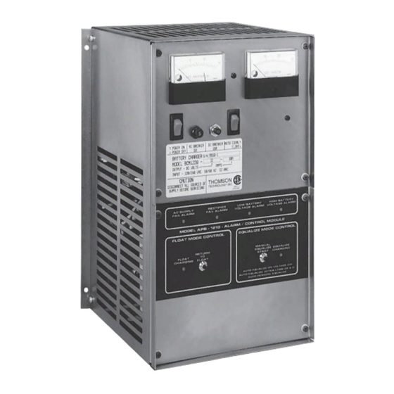
- Page 6 BCM 1220 BATTERY CHARGER OPTIONAL APB 1210 ALARM / CONTROL MODULE The optional APB 1210 alarm/control module is divided into two sections, as follows. (Any or all of these features may be provided according to requirements): 6.1. ALARM SECTION 6.1.1. A.C.Fail Indicates a loss of A.C.
- Page 7 Return of AC power supply. CONNECTION OF LOOSE APB TO BCM BOARD Insert all the way down the header female connector of APB Board into the six pin white male connector of BCM Board. Note: APB header female connector can plug in only in one direction.
Need help?
Do you have a question about the BCM 1220 and is the answer not in the manual?
Questions and answers