Table of Contents
Advertisement
Quick Links
Advertisement
Table of Contents

Subscribe to Our Youtube Channel
Summary of Contents for Akai DV-P4797KDMC
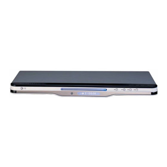
- Page 1 DVD PLAYER Model: DVP4797KDMC SERVICE MANUAL www.akai.ru...
-
Page 2: Table Of Contents
Daewoo DA Service Manual Table of Contents Page General Section..................2-5 Caution/Warnings Safe Warnings Precautions Software Upgrade Circuit Diagram and Component Layout............6-26 MPEG IC Block Diagrams Power supply Circuit Diagram and Component Layout MPEG Circuit Diagram and Component Layout Front panel Circuit Diagram and Component Layout Servicing Procedures................27-33 Power Supply Trouble Service Flow Chart Read Disc Trouble Service Flow Chart... -
Page 3: General Section
1. General Section 1.1 Cautions/Warnings 1.1.1 Product Safety Notice Parts marked with the symbol in the schematic diagram have critical char- acteristics. Use ONLY replacement pares recommended by the manufacturer. It is recommended that the unit be operated from a suitable DC supply or batter- ies during initial check out procedures. -
Page 4: Precautions
1.2.2 Laser Caution CAUTION Adjusting the knobs, switches, and controls , ect. Or taking actions not specified herein may result in a harmful emission of laser beams. This CD Changer must be adjusted and repaired only by qualified serv ice personnel. -
Page 5: Software Upgrade
1.3.2. DVD Loading Unit Precautions When handing the Mechanism Block 1.3.2.1 Do not loosen any screws in the Pickup Block. 1.3.2.2 Do not adjust any screws in the Mechanism Block except for Tilt Adjust Screws , as they are adjusted precisely at the factory. 1.3.2.3 Replacement of the Pickup Block is impossible. - Page 6 Press 1 key , Show Message on TV UPGRADE FILE DETECTED UPGRADE ? File Copy The tray is automatic to open, take disc away. UPGRADE FILE DETECTED UPGRADE ? Upgrading At this time, please wait a few minutes, DVD is downloading code to flash, After Logo will be show on TV again, the update process finish.
- Page 7 Page 6...
- Page 10 Page 7...
- Page 11 Page 8...
- Page 12 Page 9...
- Page 13 Page 10...
- Page 14 Page 11...
- Page 15 Page 12...
- Page 16 Page 13...
- Page 17 Page 14...
- Page 19 Page 16...
- Page 20 Page 17...
- Page 21 Page 18...
- Page 22 Page 19...
- Page 23 Page 20...
- Page 24 Page 21...
- Page 25 Page 22...
- Page 26 Page 23...
- Page 27 Page 24...
- Page 28 Page 25...
- Page 29 Page 26...
- Page 30 Page 27...
-
Page 31: Power Supply Circuit Diagram And Component Layout
2.2 Power Supply Circuit Diagram and Component Layout Fig2-2 Power Supply Circuit Diagram Page 28 Page 15... - Page 32 Fig2-3 Power Supply Assembly Drawing Page 29...
- Page 33 Fig2-4 Power Supply Bottom Routing Page 30...
- Page 34 Fig2-3 Power Supply Assembly Drawing Page 31...
- Page 35 Page 32...
- Page 39 Materials List Front Panel PCB A ssy Modul Part Name DVD4797 Front board Part name CR02 LED Display Connector...
- Page 40 M aterials List M odul Part No ED-DAE02-02 R Carbon Film...
- Page 41 M aterials List Power P CB A ssy Part No ED -DAE02-03 Modul...
- Page 42 M aterials List Front Panel PCB A ssy M odul Part Nam e C R 0 2 C R 0 2 C R 0 2 C R 0 2 C R 0 2 C R 0 2 C R 0 2 C R 0 2 C R 0 2 C R 0 2...
-
Page 43: Power Supply Trouble Service Flow Chart
3.1. Power Supply Trouble Service Flow Chart Power Supply Block Trouble Replace FusE1 Check FusE1 Condition Check on D1/D2/D3/D4 Output Voltage Condition Check on D6/EC2 Check on U1 Pin2 parts Voltage Condition 13-18V Replace U1 Replace T1 Check CON1 Output Voltage... -
Page 44: Read Disc Trouble Service Flow Chart
3.2. Read Disc Trouble Service Flow Chart Read disc problem in a DVD player is a very complicated issue that may involve complex issues. This problem is not only relation to the electronic circuit, but also very much relation to the operation environment. DVD loading unit is a very complicate part that contains big number of ESD com- ponents , which require specific equipment, tools and technique to repair;... -
Page 45: Video Trouble Service Flow Chart
3.3. Video Trouble Service Flow Chart 3.3.1. Composite Video Trouble Service Flow Chart Composite Video Trouble Check SETUP Item User Manual Check L3 Output Signal Replace L3 Parts Check D8 Signal Replace D8 Check C166 Signal Replace C166 Check Cp1 Pin Signal Check External Set Replace Cp1... - Page 46 5 * 1 2 m m 5 * 1 2 m m 5 * 1 2 m m 5 * 1 2 m m 6 * 1 2 m m 6 * 1 2 m m 8 * 1 2 m m...
-
Page 47: Digital Audio Trouble Service Flow Chart
3.5. Digital Audio Trouble Service Flow Chart Digital Audio Trouble Check SETUP Item See User Manual Check U Signal Replace U Check C Signal Replace Check R Signal Replace Replace Con Check External set Check Con... -
Page 48: Front Control Trouble Service Flow Chart
3.6. Front Control Trouble Service Flow Chart Front Control Trouble Replace Check SW... -
Page 49: Remote Control Trouble Service Flow Chart
3.7. Remote Control Trouble Service Flow Chart Remote Control Trouble Replace Battery Replace Control Check Remote Control Check Power Supply Check IR Pin3 Voltage Check IR Pin1 Output Replace IR Signal Check between 1CN Replace connection Replace U...


Need help?
Do you have a question about the DV-P4797KDMC and is the answer not in the manual?
Questions and answers