CFE -5100 Manual
Hide thumbs
Also See for CFE-5100:
- User manual (39 pages) ,
- Wifi manual (10 pages) ,
- User manual (12 pages)
Table of Contents
Advertisement
Quick Links
CF ENERGY CO.,LTD.
CFE-5100
Residential ESS Manual
About CFE-5100 ESS
CFE-5100 can be installed in Parallel or in Series, more attention should be paid to
the DIP and Address selection following with part 5.3.2.
About this Manual
The Manual is intended for the CFE-5100 Residential ESS. The hybrid inverter and
any other equipment are not included.
Advertisement
Table of Contents

Related Manuals for CFE CFE-5100


Summary of Contents for CFE CFE-5100
- Page 1 CFE-5100 Residential ESS Manual About CFE-5100 ESS CFE-5100 can be installed in Parallel or in Series, more attention should be paid to the DIP and Address selection following with part 5.3.2. About this Manual The Manual is intended for the CFE-5100 Residential ESS. The hybrid inverter and...
-
Page 2: Table Of Contents
Contents 1 Safety Instructions ..........................- 1 - 1.1 Important Safety Instructions .................... - 1 - 1.2 Warnings in the Document ....................- 1 - 1.3 Battery Handing Guide ...................... - 2 - 1.4 Emergency Situations ......................- 2 - 1.4.1 Leaking Battery ...................... - Page 3 7 Commissioning ..........................-28- 7.1 Commissioning of Battery ....................-28- 7.2 Shutting Down of Battery ....................-29- 8 Troubleshooting ..........................-29- 9 Firmware Update ..........................-31- RED Declaration of Conformity (DoC) ..................-32- Warranty of CFE Residential ESS ....................-33-...
-
Page 4: Safety Instructions
A warning describes a hazard to equipment or personnel. It calls attention to a procedure or practice, which, if not correctly performed or adhered to, could result in damage to or destruction of part or all of the CFE equipment and/or other equipment connected to the CFE equipment or personal injury. -
Page 5: Battery Handing Guide
Use the battery pack only as directed. 1.4 Emergency Situations The Product is designed with multiple safety strategies to prevent hazards resulting from failures. However, CFE cannot guarantee their absolute safety in uncertain situations. 1.4.1 Leaking Battery If the battery pack leaks electrolyte, avoid contact with the leaking liquid or gas. -
Page 6: Wet Battery
If the battery catches fire, it will produce poisonous gases. Do not approach. 1.4.3 Wet Battery If the battery is wet or submerged in water, do not try to access it. Contact the CFE customer careline or your distributor for technical assistance. 1.4.4 Damaged Battery... -
Page 7: Customer Careline
Use the contact below for technical assistance. This phone number is available only during business hours on weekdays ( CET ). Customer careline +86 400 996 8377 2 Product Introduction 2.1 Technical Data Model CFE-5100 Total Energy* 5.1kWh Battery Capacity (Ah) 100 Ah Nominal Charge/Discharge Power 3 kW... -
Page 8: Exploded View Of The Product
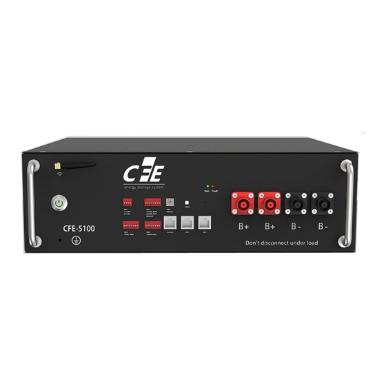
Testing Conditions Based on Temperature 25℃ at the Beginning of Life. Total Energy/Usable Energy Measured under Specific Conditions of CFE 0.2C CC/CV. 2.2 Exploded View of the Product 2.3 Indicators and Ports There are two LED indicators on the front of the battery to show its operating status. -
Page 9: Communication Interface Panel
Item Designation Definition Battery is working normally, without faults Fault Battery is in a warning state, see Troubleshooting in Chapter 8 2.4 Communication Interface Panel DIP switch selection for CAN or RS485 Resistance for communication and DIP switch for parallel connection Switch for battery’s Address select SW4 &... -
Page 10: Feature
Extra energy will be fed into the grid when Optimized self-consumption will be ESS is fully charged, and the system has achieved. ESS is used to store the excess already met its self-consumption energy produced by PV system. requirement. Evening Night If the ESS capacity is insufficient to meet ESS will power the AC load when the... -
Page 11: Installation Prerequisites
These products shall be handled with care and immediately inspected if visibly damaged. lf the carton is visibly damaged, please contact the CFE customer careline to confirm whether the battery could be used safely or not 4 Installation Prerequisites 4.1 Installation Location... -
Page 12: Installation Process
4.2 Installation Process The Product should be installed according to the following flow chart. 4.3 Installation Materials Following installation materials should be prepared by installers ✓ Power cable ✓ Communication cable ✓ Ground wire Bipolar external isolator, when two or more battery systems are in parallel, each of them shall have a bipolar isolator... -
Page 13: Tools
NOTICE Make sure that the cross-sectional area of charging cables is 25 to 35 mm2. A breaker between the Product and inverter is recommended to install, and the breaker’s min. current should be over 150A or following with local regulations. 4.4 Tools To install the battery pack, the following tools are probably required: Phillips screwdriver... -
Page 14: Communication Cable
4.6 Communication Cable If needed, the network cable should be made like the diagram shown above. But the network cable between the battery and Inverter should be made following the definition of Inverter. If available, use a LAN cable tester to check whether the cable is faulty 4.7 Storage If the battery is not to be installed immediately, or removed from operation and needs to be stored for a long period, please choose an appropriate location to store it. -
Page 15: Checks Before Installation
LED lights on, measure the voltage at the terminal interface with a voltmeter. If the voltage is lower than 48 V, do not use the battery and contact the CFE customer careline or your distributor. 5.3 Installation of the Battery... -
Page 16: Connect With 51.2Vdc Inverter
5.3.1 Connect with 51.2Vdc Inverter To prevent the battery from moving, make sure the battery is fixed to a wall NOTICE If the battery is installed above the floor or on a platform, make sure that the wall or platform is capable of supporting the battery’s weight. 5.3.1.1 Wall Mounting 1. - Page 17 The installed location shall be restricted access or installed in a cabinet which provides a guard from pets and children. 5.3.1.2 Ground Installation Meanwhile, CFE-5100 battery also could be installed on the floor, the installation steps are following: 1. Fix the holders to the battery’s mounting holes one by one.
-
Page 18: Address Selection Of Master And Slave Battery (Batteries) Connection
5.3.2 Address selection of Master and Slave Battery (Batteries) Connection For Series connection, please make sure the SW2 DIP switch of selected as this type. WARNING Please make sure the SW2 DIP switch is selected correctly. If the battery is connected in Parallel mode, but the selection of SW2 DIP8 is done at the ON position, it might lead to a serious or even dangerous fault. - Page 19 Slave 1 Slave 2 Master Slave 1 Slave 2 Slave 3 Master Slave 1 Slave 2 Slave 3 Slave 4 Master Slave 1 Slave 2 Slave 3 Slave 4 -16-...
- Page 20 Slave 5 Master Slave 1 Slave 2 Slave 3 Slave 4 Slave 5 Slave 6 Master Slave 1 Slave 2 Slave 3 Slave 4 Slave 5 Slave 6 Slave 7 -17-...
-
Page 21: Cable Connections
5.4 Cable Connections WARNING Before connecting the battery with the inverter, please make sure that no other inverter is connected and turned off. 5.4.1 Cable Connection for Series Connection NOTICE The voltage difference of each battery in series connection should be less than 100mV. - Page 22 5.4.1.2 Wall Mounting For wall mounting, the battery Series connection number should be less than 4, if more batteries need to be installed, a cabinet is recommended. NOTICE If the battery is connected in the Series mode, it is better for the Power cable resistance difference between stack and battery pack, which will have a fade effect on voltage balance, to be installed in the Ground installation method.
- Page 23 5.4.2.2 Wall Mounting For wall mounting, the battery Series connection number should be less than 4, if more batteries need to be installed, a cabinet is recommended. NOTICE Before two or more batteries are installed in Parallel, please check the voltage of each battery and make sure the voltage difference is less than 2.0V.
-
Page 24: Configuration
If parallel connecting multiple batteries, please set the DIP switches as follows: 6.1 Configure device Wi-Fi The Product has a built-in Wi-Fi module for use with the CFE APP. The Wi-Fi setting of the battery should be as follows: 6.2 App Monitor “Smart BESS” Instruction 6.2.1 Software Overview... - Page 25 Data query: Supports users to view the current voltage, temperature and other operating data of the bound battery, supports to view any 24-hour battery operation data in the data record, supports to view the battery operation status, and the off-grid status. Fault warranty: supports battery fault self-check, records battery fault status and fault information in real-time, and...
- Page 26 ➢ Search for Smart BESS in the APP Store ➢ Enter the Smart BESS application details page, click GET to install ➢ Wait for the installation of the Smart BESS installation package to complete, you can open it for use 6.2.2 Instructions 6.2.2.1 User registration ➢...
- Page 27 6.2.2.2 User Login ➢ Enter the Register page, enter the ➢ After successful registration, it will user name, email, and six-digit automatically return to the login string password, click T&Cs and page, enter the registered user name Privacy policy, you can view the and password, and click Login to user agreement, agree to the log in...
- Page 28 Add Battery、My Battery、 Warning & Services 6.2.2.5 Add Battery ➢ After the battery is connected to the 6.2.2.4 Wi-Fi Distribution Network ➢ Select Wi-Fi Config to configure network, select Add Battery to add the battery, click it to enter the battery network.
- Page 29 The battery overview details page displays the current battery cell data 6.2.2.6 Battery Management Voltage(V), Current(A), Temperature(℃), SOC; and the After completing the distribution network and adding batteries, click single cell voltage of the battery is My Battery to view the information displayed under Cell Voltage.
- Page 30 querying the 24-hour battery voltage, 6.2.2.8 Other Functions ➢ User password modification: Click charge and discharge history at any Reset Password on the login page to time point enter the password reset interface, enter the current user name in the User Name column, and enter the battery ID bound by the current user for Battery id or scan the code to...
-
Page 31: Settings For Can /485 Bus Pins
NOTICE The battery default protocol is CAN bus, if an inverter communication mode is RS485 or other protocol, please contact the CFE customer careline before installing the battery. 7 Commissioning 7.1 Commissioning of Battery... -
Page 32: Shutting Down Of Battery
If the battery fault light on, please check the Troubleshooting number on the Homepage in your CFE APP, if the code is 0x1***, this problem will recover by itself. But if the code is 0x2*** or 0x3***, please contact the CFE after service... - Page 33 4) If the registration of the battery fails, please check that the network is available and stable of the mobile phone near the battery installation site. Table 8-1 Fault Code of Battery Fault Code Detail fault message 0x1001 Battery undervoltage warning 0x1002 Battery overvoltage warning 0x1003...
-
Page 34: Firmware Update
0x2009 Cell over discharge protection 0x2010 Cell over charge protection 0x3000 Communication is broken between master and slave Battery 0x3001 Address select fault 9 Firmware Update It is possible to update the BMS firmware version manually via the Wi-Fi monitor system App. -
Page 35: Red Declaration Of Conformity (Doc)
Lithium ion battery trade name: type or model: CFE-5100 relevant supplementary information: ........(e.g. lot, batch or serial number, sources and numbers of items) to which this declaration relates is in conformity with the essential requirements and other relevant requirements of the RED Directive (2014/53/EU). -
Page 36: Warranty Of Cfe Residential Ess
E-mail:sales@cfenergygroup.com Warranty of CFE Residential ESS This warranty specified below applies to ESS supplied by CFE, CFE LFP battery to consumer through authorized reseller. The accessories and tool kits provided are not included. If the unit suffers major failure you will be provided with a replacement unit and your warranty will be transferred to the new unit. - Page 37 Product or its installation, use,performance or non-performance, or any defect or breach of warranty, whether based on contract, warranty, negligence, strict liability, or any other theory. CFE’s aggregate liabilities, if any, in damages or otherwise, shall not exceed the purchase price paid by the Original Buyer for the product.
- Page 38 Total energy/Usable energy measured under specific conditions from CFE 0.2CC-CV at DC side. But, if you suspect CFE’s verification, the Product must be tested by an EU certified origination or a certified 3rd party testing company. Meanwhile, the cost of any 3rd party evaluation service charge should beard by yourself, unless your claim is proven to be valid, in which case CFE will be responsible for the testing costs.
- Page 39 Out Of Warranty In the event the Product is out of warranty, CFE may (in its discretion) provide certain after-sales service to Original Buyer, but all the costs and expenses, such as parts, labour costs and travel expenses, shall be borne by Original Buyer. To request such...
- Page 40 -37-...
Need help?
Do you have a question about the CFE-5100 and is the answer not in the manual?
Questions and answers