Advertisement
Available languages
Available languages
Quick Links
INSTALLATION INSTRUCTIONS
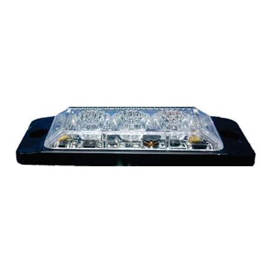
850185HP-A / 850185HP-B LED LIGHT HEAD
FAILURE TO FOLLOW THESE SAFETY PRECAUTIONS AND INSTRUCTIONS COULD
RESULT IN DAMAGE TO THE PRODUCT OR VEHICLE AND/OR SERIOUS INJURY TO
Safety Warning:
1.
Proper installation of this product requires the installer to have a good understanding of automotive electronics,
systems and procedures.
2.
If mounting this product requires drilling holes, the installer MUST be sure that no vehicle components or other vital parts
could be damaged by the drilling process. Check both sides of the mounting surface before drilling begins. Also de-burr the
holes and remove any metal shards or remnants.
3.
Do not install this product or route any wires in the deployment area of your air bag. Equipment mounted or located in the
air bag deployment area will damage or reduce the effectiveness of the air bag, or become a projectile that could cause
serious personal injury or death. Refer to your vehicle owner's manual for the air bag deployment area. The User/Installer
assumes full responsibility to determine proper mounting location, based on providing ultimate safety to all passengers
inside the vehicle.
4.
Do not attempt to activate or control this device in a hazardous driving situation.
5.
This product contains either strobe light(s), halogen light(s), high-intensity LEDs or a combination of these
lights. Do not stare directly into these lights. Momentary blindness and/or eye damage could result.
6.
Use only soap and water to clean the outer lens. Use of other chemicals could result in premature lens cracking
(crazing) and discoloration. Lenses in this condition have significantly reduced effectiveness. Inspect and operate
this product regularly to confirm its proper operation and mounting condition. Do not use a pressure washer to clean
this product.
7.
It is recommended that these instructions be stored in a safe place and referred to when performing
maintenance and/or reinstallation of this product.
8.
For this product to operate at optimum efficiency, a good electrical connection to chassis ground must
be made. The recommended procedure requires the product ground wire to be connected directly to the
NEGATIVE (-) battery post.
Mounting:
z
Place the unit against the mounting surface.
z
Mark the areas where the mounting holes are to be drilled. Confirm that no vehicle parts could be damaged
by the drilling process.
z
Using a bit size for a #304 metal screw, drill two mounting holes, A 0.5" dia. Wire passage hole(s) must also
be drilled. Thoroughly de-burr all hole(s).
z
Pass the wires through the hole(s) in the gasket and through the wire passage hole (s) in the mounting
surface. Fix the light head to the mounting surface.
Contents:
1 x 850185HP-A LED Light Head
1 x installation and Operation instructions
1 x gasket
2 x #304 mounting screws ( 3 x 20mm )
Specifications:
Size: 3" Length x 1.10" Width x 0.4" Height
Input Voltage: 12 – 24 VDC ; Input Current: Peak 0.7 Amps (12V), Avg. 0.35 Amps (12V) Lens color: Clear lens;
LEDs colors Available: Amber, Blue.
Meets SAE J595 Class 1 ; E6-65R Amber,Blue, Class 1 /E6-10R-030265 Approval
WARNING!
YOU AND YOUR PASSENGERS!
Operating Instructions:
1.
Switch Patterns:
(Yellow wires touch Red wires)
a.
To change to next flash pattern:
With the LED Light Heads switched on, momentarily apply + VDC to YELLOW wires for less than 1 second and
release
b.
To reset:
With the LED Light Heads switched on, momentarily apply + VDC to YELLOW wires more than 5 seconds and
release. LED Light Head will reset to the factory default pattern (Pattern # 0, Random)
2.
Synchronization: (More than 2 sets of LED Light Heads)
a.
First, connect YELLOW wires of all heads together, momentarily apply + VDC to YELLOW wires for more
than 5 seconds and release for Pattern # 0, Random.
b.
Secondly, momentarily apply + VDC to YELLOW wires to for less than 1 second and release for Pattern # 1,
then the synchronization will be functioned.
3.
Alternating or Simultaneous Flash: (More than 2 sets of LED Light Heads)
a.
Under Synchronization, connect WHITE wire of LED Light Head 1 to Red wires of all other LED Light Heads;
LED Light Head 1 will alternate with other LED Light Heads.
b.
If the WHITE wire not connected to Red wires, all LED Light Heads will flash together (Simultaneous flash)
4.
Flash Patterns: 13 selectable strobe patterns
No.
Flash Pattern
0
Random (all)
1
Steady
2
Single (R65)
3
Single (SAE)
4
Mega
5
Double
6
Triple
Wire Functions:
Red Wire: Power
Black Wire: Ground
Yellow Wire: Flash Pattern Set and Synchronization.
White Wire: Alternating or Simultaneous Flash
No.
Flash Pattern
7
Quad
8
Quint
9
8 Flash
10
Single - Quad
11
Single H/L
12
Single-Triple-Quint
Advertisement

Related Manuals for STRANDS 850185HP-A


Summary of Contents for STRANDS 850185HP-A
- Page 1 INSTALLATION INSTRUCTIONS 850185HP-A / 850185HP-B LED LIGHT HEAD Operating Instructions: WARNING! Wire Functions: FAILURE TO FOLLOW THESE SAFETY PRECAUTIONS AND INSTRUCTIONS COULD Red Wire: Power Black Wire: Ground RESULT IN DAMAGE TO THE PRODUCT OR VEHICLE AND/OR SERIOUS INJURY TO Yellow Wire: Flash Pattern Set and Synchronization.
- Page 2 Monteringsanvisning 850185HP-A , 850185HP-B Bruksanvisning: Kopplingschema: Röd kabel: + matning 12-24V Svart kabel: Jord/chassi (-) VARNING! Gul kabel: Växling av blixtmönster, används separat på varje blixtljus Underlåtenhet att följa dessa säkerhetsåtgärder och instruktioner kan leda eller koppla samman flera blixtljus till en återfjädrande brytare för att enkelt kunna ändra ljusmönster.
Need help?
Do you have a question about the 850185HP-A and is the answer not in the manual?
Questions and answers