Table of Contents
Advertisement
Advertisement
Table of Contents

Related Manuals for Opt Lasers PLH3D-XT8


Summary of Contents for Opt Lasers PLH3D-XT8
- Page 1 PLH3D-XT8 45W Cutting and Engraving Laser Head User Manual...
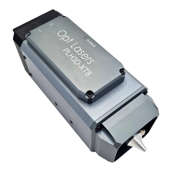
- Page 2 Thank You for Your Purchase! Thank you for choosing the Opt Lasers' PLH3D-XT8 (XT8 hereafter) laser head. Renowned for its unmatched versatility and power, the XT8 sets a new standard in the PLH3D Series for precision engraving and cutting across a broad spectrum of materials, including plastics, leather, wood, textiles, and metals like anodized aluminum, stainless steel, tool steel, and titanium.
-
Page 3: Table Of Contents
Table of Contents Technical Specifications Mounting Hole Pattern Laser Safety Important: Safety Regulations Basic Laser Safety Guidelines and Operational Protocols for Laser Head Operation Engraving Highly-Reflective Materials & Metals Electrical Inputs Pin Descriptions Working Distance Engraving Cutting Two Power Modes Cable Connection Air Assist Hose Attachment High-Pressure Air Assist Nozzle Usage... -
Page 4: Technical Specifications
Technical Specifications Performance Parameter PLH3D-XT8 Maximum Optical Power 45 W Typical Optical Power 38-43 W Wavelength 450 ± 10 nm Focused beam spot diameter <180 μm Working distance 21 mm Dimensions of Laser Head (L x W x H) 76 x 89 x 194 mm (3 x 3,5 x 7,64 in.) -
Page 5: Mounting Hole Pattern
Max. Modulation Bandwidth 30 kHz Modulation Input Impedance >1 kΩ Power Supply Unit Voltage 24 V 24 V PSU Min. Current 8.5 A Maximum Power Consumption 170 W Mounting Hole Pattern Ver. 1.1... -
Page 6: Laser Safety
Laser Safety Important: Safety Regulations The PLH3D-XT8 laser head is an accessory for your CNC machine. As the end user, it is your responsibility to prioritize and implement laser safety precautions associated with the operation and use of this laser equipment. -
Page 7: Engraving Highly-Reflective Materials & Metals
Engraving Highly-Reflective Materials & Metals When laser engraving on highly reflective materials, such as mirrors or finely polished metals, it is essential to tilt the materials or adjust the laser head slightly, introducing a small angle (e.g., 7°). This precaution is crucial to prevent potential back-reflection to the laser diodes. -
Page 8: Electrical Inputs
Electrical Inputs Refer to the image below for a visual guide to the electrical input pin. The subsequent description elaborates on its technical attributes and functionality. Pin Descriptions This is the power supply (Vcc) for the laser head, requiring 24V with a minimum current of 8.5 This is the ground (GND) for the laser head’s power supply (Vcc pin). - Page 9 Mod Input #1 ANG - optional / available on request Modulation Input #1 accepts analog or Pulse-Width Modulation (PWM) signals. The operating range of Modulation Input #1 is 0 to 5 V. If connected to a signal with a slightly higher voltage, e.g., 0 to 10 V, only the 0 to 5 V portion of the signal will affect the laser power.
-
Page 10: Working Distance
Working Distance Engraving The working distance (WD) of the XT8 laser head should be set to its nominal 21 mm (0.83 inch) between the bottom face of the laser head and the material processed, as shown below. For units purchased with the Laser Upgrade Kits this can be conveniently done using the included Height Reference Tool (HRT). -
Page 11: Cutting
Cutting For cutting thin materials (1-6 mm), the working distance should be set in such a way that the smallest beam spot is located around the middle of the material’s thickness. Start by positioning the laser at the nominal working distance (see the instructions above for Engraving) and then lower the laser head by half of the material’s thickness. -
Page 12: Two Power Modes
Two Power Modes The PLH3D-XT8 laser head offers two power modes: “I” - 50% for grayscale engraving, and “II” - 100% for high-speed black and white engraving and efficient cutting. The 50% mode, “I”, using about 0-20W, is perfect for detailed grayscale work, providing precision in shade rendering. -
Page 13: Cable Connection
In the pictures below, a short LaserDock to laser head cable can be seen. However, the same procedure applies to the Cable for PLH3D-XT8 Laser Head (7m / 22 ft). Begin by connecting the cable's connector to the laser, ensuring that the correct end of the cable (labeled 'LASER HEAD') is connected. - Page 14 If using the laser with the LaserDock Pro, plug the other end connector (labeled “LASERDOCK PRO”) into the laser part of the LaserDock Pro. Please observe the accurate position of the ST cable in the picture below. Ver. 1.1...
- Page 15 For direct connection to the PLH3D-CNC Adapter, plug the “LASER HEAD” connector to the laser, and the “CNC ADAPTER” connector to the Adapter. Ver. 1.1...
-
Page 16: Air Assist Hose Attachment
Air Assist Hose Attachment To securely attach the air assist hose to the laser head, start by threading it through the aperture in the deflector at the back of the laser. Guide it along the canal until it reaches the other end, ensuring it smoothly passes through the hole. - Page 17 If using a LaserDock Pro magnetic docking station with the laser, place the opposite end into the designated connector on the laser part of the LaserDock Pro for a seamless connection. Otherwise, connect the hose to the compressor. Ver. 1.1...
-
Page 18: High-Pressure Air Assist Nozzle Usage
High-Pressure Air Assist Nozzle Usage The PLH3D-XT8 features an advanced built-in adjustable High-Pressure (HP) Air-Assist nozzle for optimal setup in both thin material engraving and efficient thick material cutting. Always loosen the locking screw in the HP nozzle before removing, adjusting or inserting it onto the lens tube to avoid scratching. -
Page 19: Suitable Airflow
Importantly, ensure that your compressor is equipped with a filter and an oil separator to prevent the discharge of dirty air and/or oil droplets onto the laser head's lens. Failure to do so could result in protective window damage. Additionally, in humid climates, it is advisable to use an air dryer as fittings in air lines act as venturis, potentially creating condensation. -
Page 20: Laser Head Maintenance
Laser Head Maintenance Before starting any maintenance, make sure to power off the laser system to ensure safety. Disconnect the power supply to the laser head. Laser Heatsink Maintenance Heatsink maintenance is crucial for optimal performance and longevity of your laser equipment. It's recommended to blow compressed air through the heatsink regularly, especially after each use involving a significant amount of smoke or debris. -
Page 21: Laser Optics Maintenance
100 working hours. To maintain the protective window, gently unscrew the front cap part of the lens tube. In the case of protective window damage, a replacement part can be purchased from the Opt Lasers shop: https://optlasers.com/accessories/plh3d-xt8-protective-window The lens of your laser head should ideally undergo cleaning every 100 working hours. - Page 22 MG Chemicals (824) IPA (Australia) An example cleaning routine is shown in this video: https://youtu.be/MLzFjfEJGa4 Cleaning should be carried out delicately, with just enough force to remove oil drops and dirt, but not too strong to prevent damage to the optical coating. Note: Avoid using lens wipes advertised for cleaning reading glasses and microscopes on your laser equipment.
Need help?
Do you have a question about the PLH3D-XT8 and is the answer not in the manual?
Questions and answers