Subscribe to Our Youtube Channel
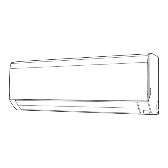
Summary of Contents for Fujitsu ASYG 18 KLCA
- Page 1 Installatiehandleiding HOOG AAN DE WAND KLC serie Binnenunit ASYG 1 8 KLCA ASYG 24 KLCA Voor gebruik door de professional. Te bewaren door de gebruiker voor toekomstig gebruik.
-
Page 2: Table Of Contents
INSTALLATION MANUAL AIR CONDITIONER Wall-Mounted Type PART No. 9319357102-02 [Original instructions] For authorized service personnel only. CAUTION • Read carefully all safety information written in this manual before you install or use the air conditioner. • Install the product by following local codes and regulations in force at the place of installation, and the instructions provided by the manufacturer. - Page 3 CAUTION CAUTION 2-Servicing 3-Repairs to sealed components 2-1 Service personnel • During repairs to sealed components, all electrical supplies shall be disconnected • Any person who is involved with working on or breaking into a refrigerant circuit from the equipment being worked upon prior to any removal of sealed covers, etc. should hold a current valid certifi...
-
Page 4: About This Product
Explanation of symbols displayed on the indoor unit or outdoor unit. CAUTION This symbol shows that this appliance uses a fl ammable 9-Charging procedures refrigerant. WARNING • In addition to conventional charging procedures, the following requirements shall be If the refrigerant is leaked and exposed to an external igni- followed. -
Page 5: General Specification
2.2. Accessories 4. ELECTRICAL REQUIREMENT The indoor unit is powered from the outdoor unit. Do not power indoor unit from separate The following installation accessories are supplied. Use them as required. power source. Name and Shape Name and Shape Operation manual Cloth tape WARNING Standard for electrical wiring and equipment differs in each country or region. - Page 6 6.1. Installation dimensions 6.4. Installing the wall hook bracket (1) Install the wall hook bracket so that it is correctly positioned horizontally and vertically. Wall hook bracket If the wall hook bracket is titled, water will drip to the fl oor. 83 mm or more (2) Install the wall hook bracket so that it is strong enough to withstand the weight of an 70 mm or more...
-
Page 7: Electrical Wiring
[Installing the indoor unit] 6.6.3. Flare connection • Hang the indoor unit from the hooks at the top of the wall hook bracket. • Insert the spacer, etc. between the indoor unit and the wall hook bracket and separate WARNING the bottom of the indoor unit from the wall. -
Page 8: Finishing
7.2. Indoor unit wiring CAUTION • Match the terminal block numbers and connection cable colors with those of the (1) Remove the intake grille. (Refer to “9.1. Intake grille removal and installation”.) outdoor unit. Incorrect wiring may cause a fi re. •... -
Page 9: Test Run
Intake grille installation 11. REMOTE CONTROLLER INSTALLATION (1) The fi xing axle of the intake grille is installed on the Panel. (2) Lay down the intake grille. Check that the indoor unit correctly receives the signal from the remote controller, then install the remote controller holder. -
Page 10: Customer Guidance
Auto restart STEP 2 Enable or disable automatic restart after a power interruption. Setting the Function Number and Setting Value (♦... Factory setting) Function Setting Value Setting Description Press the SET TEMP. ( Number ) buttons to select the function number. Enable ♦... -
Page 11: Error Codes
Error display 14. ERROR CODES OPERATION TIMER ECONOMY Error code Description If you use a wireless remote controller, the lamp on the photo detector unit will output error lamp lamp lamp codes by way of blinking patterns. If you use a wired remote controller, error codes will ap- (green) (orange) (green) - Page 12 Error display OPERATION TIMER ECONOMY Error code Description lamp lamp lamp (green) (orange) (green) High pressure error (10) Low pressure error (10) Branch boxes error (13) [Flexible multi-split type] ● Display mode : 0.5s ON / 0.5s OFF ◊...


Need help?
Do you have a question about the ASYG 18 KLCA and is the answer not in the manual?
Questions and answers