Advertisement
Quick Links
Read these instructions carefully for proper installation. After installation, keep it
in a safe place for reference when required. Refer to the user's manual in detail.
You can download the user's manual from our website.
For User's manual
https://industry.panasonic.com/
Before using, master the knowledge of the equipment, safety information and
all of other notes.
A handling error could cause serious physical injury to
WARNING
an operator and in the worst case could even be fatal.
●Always take precautions to ensure the overall safety of your system, so that the whole
system remains safe in the event of failure of this product or other external factor.
●Do not use this product in areas with inflammable gas. It could lead to an explosion.
●Exposing this product to excessive heat or open flames could cause damage to the
lithium battery or other electronic parts.
1. Before use
Eco-POWER METER is designed chiefly to manage saving energy.
It is neither intended nor can it be legally used for billing.
Eco-POWER METER is designed to be used installing in a control panel.
Please use Eco-POWER METER according to the specification described.
Otherwise, it may malfunction or cause fire and an electric shock.
·
Connect Eco-POWER METER to the power supply in compliance with the
rating.
· Refer to the wiring diagram to ensure proper wiring for the power supply,
input and output.
· Use an electric wire applicable to the rated current.
· Do not perform wiring or installation with a live line. It may also lead to circuit
burnout or fire by way of the secondary CT side opening.
Do not connect voltage input wires parallel to high-voltage or power cables
and avoid using the same conduit. Use shielded wires as short as possible.
Do not turn on the power supply until all wiring is completed and checked.
Do not use at secondary side circuit of inverter. It might cause exothermic heat
or damage.
If additional noise effects the measured line, incorrect measurements may
occur.
Installation and wiring must be performed by expert or qualified personnel for
electrical work or electric piping.
Please wipe dirt of the main unit with soft cloth etc. If thinner is used, the unit
might deform or be discolored.
Do not add an excess power to the display. It might break the inner liquid
crystal.
The in the print symbol is a double-insulated symbol for measurement.
When using in the application confirming to EN61010-1/IEC61010-1, make
sure to satisfy the following conditions.
· Overvoltage category: II,
· A minimum of dust, and an
Pollution degree 2
absence of corrosive gases
· Measurement category:Ⅱ
·
No flammable, explosive gasses
· Indoor use
· Few mechanical vibrations or shocks
· An ambient temperature of -10 to 50℃
· No exposure to direct sunlight
· An ambient non-condensing humidity
No large capacity electromagnetic switches or
cables through which large current is flowing
of 30 to 85%RH (at 20℃)
·
Altitude of 2000 m or less
Pursuant to the directive 768/2008/EC
Manufacturer : Panasonic Industry Co., Ltd.
1006, Oaza Kadoma, Kadoma-shi, Osaka 571-8506, Japan
Importer : Panasonic Industry Europe GmbH
Caroline-Herschel-Strasse 100, 85521 Ottobrunn, Germany
Contact for CE: Panasonic Marketing Europe GmbH Panasonic Testing Centre
Winsbergring 15, 22525 Hamburg, Germany
This product has been developed / produced for industrial use only.
KW2G エコパワーメータ
ご使用になる前に必ずこの施工説明書をよくお読みいただき、正しく施工してく
ださい。そのあと、大切に保管し、必要なときにお読みください。なお詳細は、
ユーザーズマニュアルをご覧ください。
ユーザーズマニュアルは 当社のホームページよりダウンロードできます。
ユーザーズマニュアル
https://industry.panasonic.com/
ダウンロードのお知らせ
安全上のご注意
ケガや事故防止のため、以下のことを必ずお守りください。
本製品の故障や外部要因による異常が発生しても、システム全体が安全側に
働くように本製品の外部で安全対策を行ってください。
燃焼性ガスの雰囲気では使用しないでください。爆発の原因となります。
本製品を火中に投棄しないでください。電池や電子部品などが破裂する原因となります。
異常発熱や発煙を防止するため、本製品の保証特性・性能の数値に対し余裕
をもたせて使用してください。
分解、改造はしないでください。異常発熱や発煙の原因となります。
通電中は端子に触れないでください。感電のおそれがあります。
非常停止、インターロック回路は外部で構成してください。
電線やコネクタは確実に接続してください。
接続不十分な場合は、異常発熱や発煙の原因となります。
製品内部に液体、可燃物、金属などの異物を入れないでください。異常発熱
や発煙の原因となります。
電源を入れた状態では施工 ( 接続、取り外しなど ) しないでください。感電
のおそれがあります。
1. ご使用前に
エコパワーメータは、省エネ目的の自主管理用の商品です。課金目的には使用
できません。また、計量法に定める指定機関が行う検定に合格した特定計量器
ではありませんので、電力量の証明には使用できません。
エコパワーメータは、制御盤内に設置して使用することを前提に設計されてい
ます。
火災・故障・誤作動や感電の原因となりますので、記載された仕様範囲内で使用
してください。
・定格にあった電源に接続してください。
・電源・入力・出力は、結線図を参照し正しく配線してください。
・全ての電線サイズは定格電流に適合したものを使用してください。
・活線工事は行わないでください。感電または短絡やCT2次側開放により故障
するおそれがあります。
計測電圧入力の入力線は、高圧線・動力線との平行配線、同一電線管配線を避
け、できるだけ短く配線してください。
全ての配線が終了するまで電源をONにしないでください。
インバータの2次側回路では使用しないでください。本体の発熱や故障の原因にな
ります。
計測する電線にノイズが加わると正確に計測できないおそれがあります。
エコパワーメータの配線作業は電気工事・電気配線などの専門技術を有する人
が行ってください。
エコパワーメータの汚れは柔らかい布などで乾拭きしてください。
シンナー類を使用した場合、本体の変形・変色などのおそれがあります。
表示部に強い力を加えないでください。内部の液晶の破損のおそれがあります。
EN61010-1/IEC61010-1を適用される用途にご使用の場合は以下の条件にて
使用してください。
・過電圧カテゴリ:Ⅱ、汚染度:2 ・塵・埃が少なく、腐食性ガスのないところ。
・屋内使用
・可燃ガス、爆発性ガスのないところ。
・使用温度範囲:−10〜+50℃ ・機械的振動や、衝撃のないところ。
・使用湿度範囲:30〜85%RH ・直射日光の当たらないところ。
(20℃にて) 結露なきこと ・大容量の電磁開閉器や大電流の流れている電線
・標高2000m以下
から離れているところ。
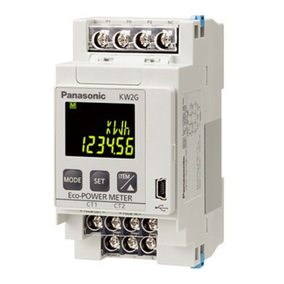
2. Part Names and Functions
Power supply
(Measured voltage
input) (M3.5)
Display
<MODE> key
<SET> key
<ITEM/ ∆ > key
Switch display items
and set values
I/O terminal(M3)
Communication
terminal (M3)
3. How to mount
How to connect the expansion unit
· Turn off the power when connecting the expansion units.
· Peel off connector label on the side before connecting.
· (Do not peel off connector labels when not connecting.)
· It expands by connecting each male connector to female connector on
the each side.
· After connecting, push the hooks into the unit to fix the expansion units.
· Up to 7 expansion units can be connected per one main unit.
Caution) Communication will be stopped or the measurement data will be
lost when the units are removed or connected with the power on.
DIN rail mounting
Mounting
Push
Weigth
Approx.180g
4. USB port
It is necessary to install USB driver in order to connect PC to USB port of
KW2G Eco-POWER METER. Refer to the Userʼs manual in detail.
5. Wiring
Use dedicated current transformer (CT) for power measurement.
Wiring Diagrams
· Be sure to wire according to the wiring diagrams.
Install a breaker (3 to 15 A) etc., in order to protect and maintain the unit.
Panasonic Industry Co., Ltd.
1006, Oaza Kadoma, Kadoma-shi, Osaka 571-8506, Japan
2. 各部の名称とはたらき
保 管 用
施 工 説 明 書
電源端子
(計測電圧入力端子)
基本ユニット
(M3.5)
液晶表示部
MODE キー
SET キー
ITEM/△キー
計測値の
表示項目変更や
設定をします
入出力端子 (M3)
通信端子 (M3)
3. 設置方法
◆増設ユニット接続方法
・増設ユニットを接続する際は、必ず基本ユニットの電源をOFFにしてください。
・接続する前に、各ユニット側面のコネクタラベルをはがしてください。
接続しない場合は、コネクタラベルをはがさないでください。
・上下のフックを外側に引き出し、各ユニット側面の増設コネクタ(オ
ス)を増設コネクタ(メス)に接続して増設していきます。
・接続したあとは、フックをユニットの内側に押し込み、増設ユニットを
固定してください。
・基本ユニット1台に増設ユニットは最大7台まで接続できます。
注)電源を入れたままの状態で、ユニットを外したり接続したりすると、通信が途絶え
たり計測データなどが消失したりしますのでご注意ください。
◆DIN レール取付方法
取り付け
押す
取り付け時は DIN フックの
位置を確認してください。
4. USBポー トについて
KW2GエコパワーメータのUSBポートにパソコンを接続するためには、USBドライバの
インストールが必要です。詳細はKW2Gエコパワーメータユーザーズマニュアルをご覧ください。
パナソニック インダストリー株式会社
〒571-8506 大阪府門真市大字門真1006番地
Unit number
Display
indicator
Show the unit
P1 P0 P2 NC
number to
display
LOCK indicator
Key operation is
invalid while
lighting
Mode indicator
Display setting
items
Measurement
OUT indicator
value
Lit during pulse output
TX/RX indicator
Lit while communication is
+ PULSE OUT- + PULSE IN-
established
USB port
Connector for Current
RS485 + - E
transformer(CT) (below side)
Expansion
Expansion
Hook
Hook
Hook
connector
connector
(male)
(male)
Hook
Hook
Connector label
Removing
Hang
Displace
Lift
Check the position of DIN hook before mounting.
https://industry.panasonic.com/
Please visit our website for inquiries and about our sales network.
液晶表示部
P1
P0
P2
NC
(全てを表示させた状態)
ユニット番号表示
表示している
ユニット番号が点灯
LOCK
インジケータ
点灯中は
キー操作でき
ません
モード項目表示
OUT インジケータ
設定項目などを
接点出力時に点灯
表示
TX/RX インジケータ
各計測値表示
+ PULSE OUT-
+ PULSE IN -
通信中に点灯
USB ポート
電流センサ (CT) 用コネクタ
RS485 +
-
E
(図示の側面にあります)
フック 増設コネクタ
フック
フック
増設コネクタ
(オス)
(オス)
フック
フック
コネクタラベル
◆JIS 協約形取付金具 取付方法
取り外し
取り付け
取り外し
※
下げる
引っかける
押す
ず らす
引っかける
持ち上げる
取り付け時は DIN
フックの位置を確
認してください。
※複数の増設ユニットを接続した場合は取付金具
のバネを押し込むと取り付けやすくなります。
https://industry.panasonic.com/
<FAデバイス技術相談窓口>TEL:0120-394-205 受付時間:9時~17時(12~13時、当社休業日を除く)
Single-phase two-wire
One CT is needed. (Two CTs are needed when measuring 2CH.)
1
Main
breaker
2
Breaker for
Eco-POWER METER
Short 1 and 3
for measuring
2-circuit
P1
P0
P2
N.C.
Single-phase two-wire
1
2
3
4
1
PULSE OUT PULSE IN
2
+ ‒
+ ‒
440 V
5
6
7
8
110 V
9
10
11
+ ‒ E
RS485
Single-phase three-wire/three-phase three-wire
R
R
1
Main
N
S
2
breaker
T
T
3
Breaker for
Single-phase three-wire/
Eco-POWER METER
three-phase three-wire
P1
P0
P2
N.C.
R
R
1
2
3
4
N
S
T
T
PULSE OUT PULSE IN
+ ‒
+ ‒
5
6
7
8
9
10
11
+ ‒ E
RS485
The input voltage to each terminal is as follows.
Phase and
Terminal
Terminal
wire system
1P2W
P1 - P0
Measured
1P3W
P1 - P0 - P2
voltage input
3P3W
P1 - P0 - P2
Power supply
100 - 240VAC 50/60Hz 6VA (15VA max.), Allowable supply voltage: 85-264V AC
Expansion unit (Power measurement, Power measurement and Pulse output, and Analog input): 0.5 VA / unit,
Expansion unit (Pulse input): 1.0 VA /unit
◆Caution for Wiring
◆How to attach the Current Transformer (CT)
1) Use the CTs with the same rated capacity for
1) Terminal fastening torque should be 0.5 to 0.6
N·m for M3 screw and 0.8 to 1.0 N·m for M3.5
one unit of Eco-POWER METER.
screw.
2) Check beforehand that the diameter of the
When using a crimp terminal, it should be with
electric wire is smaller than the through-hole of
insulation sleeve applicable to each screw.
the CT.
2) Voltage input part has no built-in power
3) When connecting CT, connect the connector to
switch, circuit breaker or fuse.
the main unit first, then connect the primary side
Connect a power switch or a breaker to the
to a load electric wire. Incorrect order might cause
voltage input part for safety reasons and to
an electric shock or break CT.
protect the device. It must be set at the position
4) CT has polarity. Wire correctly according to the
easily reached, and displayed it functions as the
K and L marks. Wrong direction canʼt measure
breaker of the equipment.
correctly.
3) We recommend a wire with the cross section of
5) When closing CT, check that there is no foreign
0.75 to 1.25 mm² (AWG18 to 16) for power supply
materials on the divided face. And make sure it is
and voltage input.
closed securely once the wire is in place;
4) Use wire less than 10 m for input and less than
otherwise the measurement value will not be
100 m for output.
accurate.
5) Use a flame-resistant cable for all wiring.
6) When CTʼs cable is extended, it is possible to
extend up to about 10 m with the cable cross
◆RS485 Wiring and Terminal setting
section of AWG22 (0.33 mm²) environment
1) When using shielded cable for RS485
without noise at all. Please use the thick cable as
transmission line, ground one end.
much as possible.
Use a class D (grounding resistance of 100 Ω or
7) Only same color housing of cable and
less dedicated earth for grounding.
connector of CT can be connected.
2) Be sure to connect with daisy chain the RS485
That of different color (blue and white) can't be
transmission line between each unit. Do not use a
connected.
splitter.
3) With a terminal station, RS485(E) and RS485(-)
should be shorted.
© Panasonic Industry Co., Ltd. 2011-2024
April, 2024
5. 配線
電力計測には、専用電流センサ(CT)をご使用ください。
◆結線図
端子結線は、結線図を参照のうえ、間違いなく確実に行ってください。
ユニットの保護やメンテナンス性確保のため、ブレーカ(3〜15A)などを設置してください。
単相 2 線式
CT:1 つ (2CH 計測時は 2 つ ) 必要
電
1
メイン
源
ブレーカ
2
側
エコパワーメータ
保護用ブレーカ
2 回路計測時は
①③端子を
渡り配線
VTの配線例
N.C.
P1
P0
P2
1
2
3
4
電
パルス出力 パルス入力
源
+
−
+
−
側
440V
5
6
7
8
9
10
11
+ − E
RS485 通信
単相 3 線式 / 三相 3 線式
CT:2 つ必要
R
R
1
電
メイン
源
N
S
2
ブレーカ
側
T
T
3
エコパワーメータ保護用ブレーカ
VTの配線例
P1
P0
P2
N.C.
1
2
3
4
パルス出力 パルス入力
+
−
+
−
5
6
7
8
9
10
11
+ − E
RS485 通信
各端子に入力する電圧は表の通りです。
端子
相および線式
端子間
単相2線
P1 - P0
計測電圧入力
(操作電源)
単相3線
P1 - P0 - P2
①②③
三相3線
P1 - P0 - P2
◆配線上の注意
1)計測電圧入力端子ネジ(M3.5)の締付トルク
は、 0 .8 〜 1 .0 N・ m 、 その 他の 端子ネ ジ
(M3)の締付トルクは、0.5〜0.6N・mで緩
みのないように締め付けてください。圧着端
子を使用する場合は、各ネジに適合する絶縁
スリーブ付圧着端子を使用してください。
2)操作電源(計測電圧入力端子)には、電源ス
イッチ、ブレーカ、およびヒューズなどの保
押す
護回路を内蔵していません。機器保護のた
め、保護回路を別途設け、容易に手が届く位
置に配置し、それが機器の遮断装置であるこ
とを表示してください。
3) 計測電圧入力端子への配線は、断面積0.75〜
1.25mm² (AWG18〜16)の電線を推奨します。
4)入力の配線は、10m以下、出力の配線は
100m以下で使用してください。
5)各種電線は、難燃性の電線(UL線など)を 使
用してください。
◆RS485 配線と終端局の設定
1) RS485伝送路はシールドケーブルを使用し、片側接地としてください。また、接地
は専用接地とし、D種接地してください。
2)RS485伝送路は、各局間を渡り配線してください。タコ足配線(分岐)はできません。
3)終端局では、RS485(E)端子と、RS485(−)端子を短絡してください。
© Panasonic Industry Co., Ltd. 2011-2024
2024年4月発行
K → L
Breaker
CT1
for load
K → L
Breaker
CT2
for load
Main unit
* In order to measure load
over rated voltage, a
voltage transformer is
VT*
needed.
Short 1 and 3 for
Use commercial VT those
measuring 2-circuit
secondary rating is 110 V.
Breaker
1
2
3
4
Eco-POWER METER
Two CTs are needed.
K → L
CT1
Breaker
for load
K → L
CT2
Main unit
1
In order to measure load
*
2
3
over rated voltage, a
voltage transformer is
440 V
needed.
Use commercial VT those
110 V
VT*
secondary rating is 110 V.
Breaker
1
2
3
4
Eco-POWER METER
Input voltage
100 - 240VAC (100 - 240V~)
(Line voltage)
100 - 120VAC (100 - 120V~:3W)
(Phase voltage)
100 - 240VAC (100 - 240V 3~)
(Line voltage)
〜:AC symbol
PRINTED IN JAPAN
K →L
負
負荷保護用
CT1
荷
ブレーカ
①
K →L
負
負荷保護用
CT2
荷
ブレーカ
②
基本ユニット
単相2線式
※定格電圧を超える負
1
荷を計測する場合は、
2
計器用変圧器 VT が
VT※
必要です。
2回路計測時は
VT は、市販の 2 次側
110V
①③を渡り配線
ブレーカ
定格 110V のものを使
用してください。
1
2
3 4
エコパワーメータ
K →L
負
CT1
負荷保護用
荷
ブレーカ
K →L
①
CT2
単相3線式/三相3線式
基本ユニット
電
R
R
1
※定格電圧を超える
源
N
S
2
側
T
T
3
負荷を計測する場合
は、計 器 用 変 圧 器
440V
VT が必要です。
VT は、市販の 2 次
110V
VT※
ブレーカ
側定格 110V のもの
を使用してくださ
1
2
3
4
い。
エコパワーメータ
入力電圧
100 - 240VAC (100 - 240V~)
(線間電圧)
100 - 120VAC (100 - 120V~:3W)
(相電圧)
100 - 240VAC (100 - 240V 3~)
(線間電圧)
◆電流センサ (CT ) の取付け
1) 1ユニットのエコパワーメータに使用する
全てのCTは同じ定格容量のものを使用して
ください。
2) あらかじめ負荷電線の太さがCTの貫通穴
径より小さいことを確認してください。
3) CTの接続の際は、必ず先にCTのコネクタ
を本体に接続し、そのあとCTを負荷電線
に配線してください。順序を間違えると感
電のおそれやCT故障の原因となります。
4) CTには極性があります。CTに記載のあ
る方向 (K→L ) にあわせて、電源側から
負荷側に向けて取り付けてください。方
向を間違えると正しく計測できません。
5) CTを取り付け閉じる際には、分割面にゴミや異物
などがないことを確認してください。また閉じた時
には、分割面が密着していることを確かめてくださ
い。分割面にすき間があると計測誤差が生じます。
6) CTのケーブルを延長する場合、ノイズを全
く受けない環境下ではAWG22(0.33mm²)
以上のケーブルで約10mまで延長できま
す。極力太いケーブルを使用してください。
7)CT中継ケーブルハウジングとCTコネクタは
同色の物のみ接続可能です。異色(青・白)組
合わせでは接続出来ません。
8A3 B69 7000 8
PRINTED IN JAPAN
Advertisement


Need help?
Do you have a question about the KW2G and is the answer not in the manual?
Questions and answers