Advertisement
Quick Links
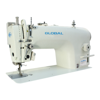
SINGLE NEEDLE DIRECT DRIVE NEEDLE FEED
LOCKSTITCH MACHINE WITH THREAD TRIMMER
3201 AUT SERIES
INSTRUCTION/ OPERATING MANUAL
Used sewing machines
Gebrauchtmaschinen
Maquinas usadas
Machines occasion
WWW.IM CA.NET
GLGBAL
PARTS MANUAL
GL@iSAL
New sewing machines
Neue Niihmaschinen
Maquinas nuevas
Machines nouveaux
Spare parts for Global machines
INFO@IMCA.NET
HO HSING
SEIM> PtOrORS
European distributor
of HO HSING
motors
Advertisement

Subscribe to Our Youtube Channel
Related Manuals for Global 3201 AUT Series


Summary of Contents for Global 3201 AUT Series
- Page 1 GLGBAL 3201 AUT SERIES INSTRUCTION/ OPERATING MANUAL PARTS MANUAL GL@iSAL HO HSING SEIM> PtOrORS Used sewing machines New sewing machines Spare parts for Global machines European distributor Gebrauchtmaschinen Neue Niihmaschinen of HO HSING Maquinas usadas Maquinas nuevas motors Machines nouveaux Machines occasion WWW.IM CA.NET...
- Page 2 Toanlc you _., much for buying our company's sewing machine. Before using ,ix.- new machine. � ,_ Ille ..r.ty insUuCli below and 1he explanations giyar, In 1he Instruct manual. Will> Industril sewing "'81:hlies, It Is normal 10 carry out work while positiu, M!d dinlcllv in front of ITllllll pens such IS Ille ,_., and 1hnBI lake -up -••...
- Page 3 2. Notes on safety _A.DANGER WIit at least 5 minutes ufter turning off the power switch and cfosconnecting the - COid from the well outlet before quy. opening the face plate of the oontml boo<. Touchin g araas where high """8gas.,, present can result in_. A,cAUTION Environmental requirements Use the sewing machine In an area which Is frae from...
- Page 4 CAUTION Sewing /<::'\ This sewing machine slwd only be used by operatot At1Bch all safety davioe • before using lhe sewing ma \.Y who ...,,, received lhe necessar lrl!ining in safe uoe � chine. If the machine is used without If-. - attached - nd.
- Page 5 3. Warning labels. The following wamiflg labels appear on the sewing machine. Please follow the instructions on the labels at all times wh"'1 usin9 the machine. If the labels have been removed or ere difficult to read, please contact your nearest dealer. CAUTION &...
- Page 6 1. NAMES OF MAJOR PARTS 1 , Bobbin winder 2. Thread wiper 3. LHtlng lever 4. Quick reverse(Actuator) 5. Presser foot 6. Control box 7. Knee lifter assembly 8. Power switch 8. Oil gauge window 10. Reverse lever 11. Stitch length dial 12.
- Page 7 2.INSTALLATION CAUTION A) Do not connect the power cord until installation is f::'\ Machine installation should only be carried out by e corn -plete. The machine may operate ii the treadle is \..)l qualilied technician. de-pressed by mistake, which could result in injury. Contact your deeler o r a qualified electrician for any Use both hands to hold the machine heed when tilting electrical work that may need to be done.
- Page 8 1 2-1.Table processing diagram The top of the table should be 40 mm in thickness and should be strong enough to hold the weight and with -stand tha vibration of tha sewing machine. Drill holes as indicated in th1 Hlustmion blllow..
- Page 9 3.Power switch (1 )Power switch. (2JScrews (2 pcs Operator 4.0il pan (1) Head. cushions 12 pcs l (left) (2)Head cushions (right) 12 pcs I (3) Oil pen. 6.Rubber cushions (l)Rubber cushions[2 pcs) (2)Nails [4pcsJ 6.Knee lifter complying bar (3) Knee lifter complying bar...
- Page 11 11. Knee lifter pla111 (1) Knee lifter plate j'[J[J (2) Bolt L.Qosen the bolt (3) and move the knee lifter plate (1) to a position where it is easy use. <Knee lifter adjustment> '-./ 1. Tum the machine pulley so that the feed dog is below the top of the needle plate.
- Page 12 I 2-3. Lubrication ,AcAUTION ((:\ Do not oonnect the power cord until lubrication has been completed, otherwise the machine may operate if the treadle is depressed by mistake ,which could result in injury. ((:\ Be sure ID weer protective goggles and glOV9S when handing the lubricating 011 and -,-, ao 1hat !hey do not get into your eves or onto your ski n , otherwise inflammation can result Fur1hermore, do not drink the oil er eat the grease under any circumstances, as the'( CBI cause vomiting and diarlhea.
- Page 13 2-4 Test operation (Operating the treadle) CAUTION Do not toUCh any of the moving pans or press any objects against the machine while sewing , as tl1iil may result in personal injury or damage to the machine. <Turning on the power> P,- 1he Off power swftch{1) The power indic:atot{2)will Hluminate.
- Page 14 3. PREPARATION BEFORE SEWING Installing the needle 13-1. CAUTION Turn off the power switch before installing the needle. The machine may operate if the treadle is depressed by mistake, which could result in injury 1. tum the machine pulley to move the needle bar to its highest position.
- Page 15 1 3-3. Winding the lower thread CAUTION J � 1-- --- --- ------" Do not touch any of the moving parts or press any objects against the machine while the IOW9r thread. as this �may result In personal injury or damage to the machine. 1.
- Page 16 I 3-5 Threading the upper thread _A.CAUTION A. Tum off the power switch before threading the upper thread. � The machine may operate if the treadle is depreased by mlstake. Which could result in injury . Tum the machine pulley end raise the thread take-up (1 ) befor9 threading the upper thread.
- Page 17 3-7 Using the thread wiper Presa the thread wiper switx:h (1) to tha n side. If this is done , the thread wiper (2) will operate a'fiir the thread is trimmed. I 3-8 Using the knee lifter The presser foot 121 can be raised by pressing the knee lifter plate{ 1).
- Page 18 4. SEWING .A.cAUTION Attach all safety devices before using the sewi�g machine. If the machine is used without these devices attached, injury may result Turn off power switch switch at the following t i mes. The mach i ne may operate if the treadle is depreased by mistake, which could result in injury. When threading the needle.
- Page 19 1 4-3.Sewing condensed stitches • When you press the rev&rse switch Ill, 1h11 sewing stitches will be on the reverse direction; while pressing the reverse lever (2),you can get the small stitches (for ward direction}, namely, condensed stitches. I Sewing direction Condensed stitches <...
- Page 20 5. THREAD TENSION I 5-1. Adjusting the thread tension AcAUTION Turn off the power switch before removing or inserting the bobbin case. � The machine may operate if the treadle is depressed by mistake. which could result in injury. Good even stitches. - Upper thread - Lower thread Upper thread tension too weak...
- Page 21 5-2.Adjusting the presser foot pressure Correct Stitch e s Upper thread Skipped stitches occur Increase the pressure. ven stitch lengt h =======:x:==== I ., . II l • i tc _ h _e _ s_a r _ e _ p_ u _c k _e_, ed __,-+ .__o_e _ c r _e _ • s _ e _ t h _e _ p _ r e _s s _ u _r e _ . ___ _ _______, ,.
- Page 22 6.CLEANING A_CAUTION Tum off the power switch before carrying out cleaning. The machine may operate ii the treadle is depressed by mistake, which could result in injury. Be sure to wear protective goggles and gloves when handling the l ubrication oil and grease, so that they do not get into your eyes or onto your skin, otherwise inflammation can result.
- Page 24 B. Oil tank oil quantity. Check the oil gauge window (1 ), and add more oil if the oil gauge {2) is below the lower reference line. Upper rererence -=,_.,. line Lower rererence 3. Checking 1. Replace the needle if it is bent or if the tip is broken. 2.
- Page 25 ------------- --- --- s-2. Applying grease <Al)l)lying grease> Use our company specified grease. 1. Turn the power switch to 'OFP 2. Remove the screws and the set screws. 3. Apply grease to each of the holes until the grease overflows slightly. 4.
- Page 26 7. ADJUSTING THE ROTARY HOOK LUBRICATION AMOUNT CAUTION Be careful not to touch your fingers or the lubrication amount check she et against n'IOlling parts such as the rotary � hook or the feed mechanism when checking the amount of oil supp l ied to the ro1Bry hook. OlhelWise injury may result.
- Page 27 8. STANDARD ADJUSTMENTS __ _ __ ___! � � _ A _ UT _ I _ ON ________ , _ _ _ _ ---1 f(;'\ Maintenance and inspection of the sewing machine Tum off the power switch end disconnect the power \Y should only be carried out by a qualified technician.
- Page 28 s-2. Adjusting the thread take-up spring <Tlvaad take-up spring position> The standard position of the thread take-up spring 11) is 6- 8mm[4-6mm for H specification s )above the surface of the thread guide(31when the presser foot is lowered. 6-8mm 1. Lower Iha presser foot (2). 2.
- Page 29 Adjusting the presser foot height 18-4. The standerd height of the presser foot 11) is 6mm when the presser foot 11) is reilled by means of the lifting lever (2). 1. Loosen the nut 13) of the adjustment screw 14),and then tum the adjustment screwl4)so that there is no pressure applied to the preaser foot .
- Page 30 .:: :'i P'!-3 � § ��� , � ; = = = =8· ((@')_ 8 • :::: ! s - 6 .Adjusting the feed dog angle The standard angle is for the feed dog (1 I to be parallel ID the needle plate when the machine pulley is turned forward to raise the feed dog from its lowest position until it is flush with the top of the needle plate.
- Page 31 7. Adjusting the needle bar height Adjust so \hgt the distance from nMdle plate mounting sur• face to the bottom edge of the needle bar is the same as the height of surface B on th e < 1 > side of the acoe95ory timing gauge when the needle bar 11) is at its lowest po...
- Page 32 I B-9 .Adjusting the needle and rotary hook timing When the machine p,.1llev is tumed forward to raise the needle bar 11) 1.8mm (2.2mm for H specifications} from its lowest position . the roterv hook tip 131 should be aligned with the canter of the needle (4) as shown in the illustration when the distance from needle plate mounting surface C to the bottom edge of the needle bar 11 l is the same as the...
- Page 34 ls-12. Adjusting the actuator position The inslallation position for the actuator (1 )can be adjust ed to <A> or <B>. Adjust so that it is in a position where it is easy to oper ate. 1. Remove the two screws (2). Back 2.
- Page 35 . Adjusting the thread trimming timing Remove the presser foot, needle plate a nd feed dog. y-(1) <Thread trimming cam position adjustment> 1. Tum the machine pulley forward to raise the needle bar (1) from its lowest pos�ion until the distance from needle plate mounting surface to the bottom edge of the needle bar (...
- Page 36 9-2 . Adjusting the needle feeding Needle deflection adjustment • Check that the needle bar (1) and the presser bar (2) are parallel when the stitch length dial is set to and the machine pulley is tumed. < Adjustment method if the needle bar (1) and presser bar (2) are not parallel >...
- Page 37 ------- -- - 3) Adjusting the needle feed amount The needle feed amount can be set to 1.2 times (20%) greater than the standard needle feed amount. Adjust the needle feed amount when sewing heavy-weight materials and materials which slip easily. 1 Remove the face plate.
- Page 38 REPLACING PARTS CAUTION Use both hands to hold the machine head when Replacement of parts should only be carried out by a � tilting it back or returning it to its original position. If qualifie d technician. only one hand is used, the weight of the machine Use only the proper replacement parts as specified head may cause your hand to slip, and your hand by Brother.
- Page 39 11 . T ROUBLESHOOTING • Please check the following points before coiling for repairs or servil:l, • If the following remedies do not f0< the problem, tum off the power switch and consult a qualified technician or the place of purchase.
- Page 40 Problem Possible cause • 5.Sldpped stitches at sewing start Is Iha thread take-up spring tension too strong? • Thread unravelHng at sawing start Reduce the tension of the lhread take-up spring. Is the thread take-up spring operating range too large? •...
- Page 41 Problem Possible cause 9.Lowar thread is tangled at • Is the bobbin spinning direction correct when the lower threed is being pulled? the s-ing start Set the bobbin so that it turns in the opposite direction to the rotary hook. SpiMing of bobbin durin g •...
- Page 42 Possible cause Problem 14.0il gauge (1 Jis not ris� • Is u,e oil tank empty? Fill the oil 111nk with oil. ble in oil gauge win - dow. 15.Machine dolls not op- • Is the power supply connector disconn&C18d from the control box? 8111te when pc,wer is lnselt the connector securely.
- Page 43 LOCKSTITCH MACHINE WITH THREAD TRIMMER rt& 3201 AUT SERIES GLGBAL HO HSING SE.IM> MOTORS Used sewing machines New sewing machines Spare parts for Global machines European distributor Gebrauchtmaschinen Neue Niihmaschinen of HO HSING Maquinas usadas Maquinas nuevas motors Machines occasion Machines nouveaux WWW.IM CA.NET...
- Page 44 ..{]--- ■ ■- o _ _ ..· - r---..C") ..-'-..())-- .� @)III-@- � ... LO __ _ ,...
- Page 45 length Rubbei RuUbm· Rub];e•· assy 2170fl026 8X76;-l29000 1. MACHINE BODY Description Note Ref. No. 217N0002:l dial Stitch BXF99 04009 Stand, R BXF9903009 Stand, L Motor BXF6851009 cover B048509894 Screw M5xl2 BXF377 4009 Side plate BX/8817009 lC:it' d �-J;i�ff. l N [r ns.
- Page 46 • ----. ---=---· : � ----- 6--j -· ,. , ..__...
- Page 47 Ll 7N0002J Rub)wr· Rub1H:1· R-swi tch assy r·,1;1 1. MACHINE BODY Description Ref. No. Note J cnst h St i1d1 pi;; 8XF9904009 Stand, R 8XF9903009 Stand, L Motor 8XF6851009 cover 8048509894 Screw M5x12 8XF3774009 Side plate BX78H17009 ir.:!.<t! � \;· i':k iEIT·f ffil fl8. l 1. 4H f"djJ HXF8930009 St iti:d.
- Page 49 �] 7\00001 �-17\0000'..'. Thread take - up support shaft �11,01000 cl7,0llll0 4-6-7 3. NEEDIE BAR AND THREAD TAKE-UP MECHANISM Ref. No. Description Note BXF3286009 Upper shaft assy BX87459009 Screw M6x6 BXF9980009 Bobbin winder driving wheel BX87459009 Screw M6x6 1 -4 BX85875009 Screw MS 1 - 5...
- Page 50 r--- 1�...
- Page 51 B098::i0tJ.77'l 3. NEEDIE BAR AND THREAD TAKE-UP MECHANISM Ref. No. Description Note BXF9960009 Joint unit 20-1 BX87459009 Screw M6x6 20-2 BXF8850009 Timing pulley, U 20-3 BX72398009 Flange 20-4 BX72397900 20-5 B048607598 Screw M4x35 20-6 S8A3103011 Spring washer 4 20-7 B085060878 Washer M4 B959516009 Needle bar thread guide...
- Page 52 L----- - - --- - 7 2 -...
- Page 53 4 NEEDLE FEED MECHANISM Description Ref. No. Note BXF3752909 Needle feed regulator arm D BX87459009 Screw M6x6 B990743009 Washer 8 BXF3751909 Needle feed regulator connecting rod 217100043 Link pin Screw M5x5 B098500574 BXF3749909 Needle feed regulator arm U B092509674 Bolt M5xl4 BXF3385009 Regulator arm electric pin BOfi'.'.
- Page 55 4. NEEDLE FEED MECHANISM Description Ref. No. Note B098600674 Screw M4X4 BXF3721809 Needle feed shaft B098040574 Screw M6X5 BXF3627809 Needle feed shaft metal R BXF3625909 Needle feed shaft metal L BXF3284009 Needle feed shaft metal M BXF6522009 Tighten ring B098500574 Screw MSXS BXF6815009 Bush R...
- Page 56 1 9 - e - 36 ----- 3 1 --fi w- - -4 5, - - 1:::i...
- Page 57 5 PRESSER FOOT MECHANISM Description Ref. No. Note BXF9939009 Presser bar For M BXF9937009 Presser bar For H BXF3868009 Presser bar bush BXF9936009 Presser adjusting screw M14 BXF3403009 Spring guide B969382009 Presser bar spring B960603009 Washer m1101000 Presser foot assy For M 027701100 Presser foot assy...
- Page 59 Screw M5x14 BXF ;5 7. ' ( )009 BXF98·l7U09 6. FEED MECHANISM Ref. No. Description Note BXF3251009 Stitch length dial assy BXF6616009 Screw SM4. 76 124510003 0 ring 217\00021 Screw bar Dial for stitch length regulator 217\00022 For M BXF3684009 Dial for stitch length regulator For H BX50012009...
- Page 60 31-2...
- Page 61 BXF:H?.4f10� 6 FEED MECHANISM Description Ref. No. Note B048509694 M5x14 Screw M5xl4 BXF9884909 Feed regulator shaft L B906661009 Rubber cap 15. 5 BXF9883909 Feed regulator support shaft BXF9882009 Rubber cap 14. 5 B098040574 Screw M6x5 BXF9881909 Screw M6x6 BX87459009 Screw M6x6 OOICOOOlO Rubber cap label BX76758909...
- Page 63 l··:'. 7 QUICK REVERSE MECHANISM Ref. No. Description Note llXF32!j9009 Quick reverse solenoid assy BXF3106009 Solenoid plate F I -2 BXF3103009 Solenoid plate B B048500294 Screw M5x8 BXF3107009 Solenoid base B048500294 Screw M5x8 B048049094 Screw M6x10 BXF8258009 Solenoid lever BXF8266009 Solenoid lever shaft BXF8262009 Set collar assy...
- Page 64 �- · ---...
- Page 65 Set collar 7. QUICK REVERSE MECHANISM Description Ref. No. Note BXF325�009 Quick reverse solenoid assy BXF3106009 Solenoid platP F BXF3103009 Solenoid p]alP 13 B048500294 Screw M5x8 BXF3107009 Solenoicl lms<> B048500294 Screw M5x8 B048049094 Screw M6xl0 BXF8258009 Solenoid lever BXF8266009 Solenoi rl l evPr shaft Set collar assy BXF8262009 7- 1...
- Page 67 217100036 Pump bush unit 0 ring S25 BXF32700CID Bobbin For M 9 ROTARY HOOK MECHANISM Description Ref. No. Note BXF3849909 Rotary hook shaft assy BXF3962009 Screw cap Screw M5-0.8 strJpper BXF3SA-S909 Rotary hook shaft BXF3847709 BXF3846009 Pump bush 2 - 2 BX8.lfi08001J Oil seal 2- 3...
- Page 68 1-ocJf...
- Page 69 10. LUBRICATION MECHANISM Description Ref. No. Note B029006030 0 ring P4 Felt BXF6830009 BXF4085009 Felt support 0 ring P4 B029006030 BX06470000 Needle bar cork Plunger 0:1640001.5 BX67605909 Pump cap screw assy BX85720609 Screw B966234009 Spring compression Rubber cap 10. 5 B906289009 BX85729009 Adjusting screw...
- Page 70 � r __ _1.__ 14-5 ______ !� I GJ- - � � i OJ) - 1 1 4- 2...
- Page 71 1-ii BXF494300Y Set screw M5x5 LI 7\00007 217\000IJfi 217\()000:J assy 11 THREADING MECHANISM Description Ref. No. Note BXF8758909 Pre-tension assy BXF8748009 Thread guide BX65547009 Thread guide tension stud 1 -3 B966506009 Thread guide disc BXF8752909 Pre-tension spring Tension nut 1-,.h BXr8747009 Pre-tension base B098500574...
- Page 72 � �...
- Page 73 12 BOBBIN WINDER MECHANISM Description Ref. No. Note BXF9139909 Bobbin winder unit B062060768 Retaining ting E4 BXF9135009 B-winder shaft support assy 1-2-1 BXF9117009 Copper bush 1-2-2 BXF9134009 B-winder shaft support BXF9132009 Bobbin winder shaft 1- 4 217102002 0 ring <D9. 5x<1>2. 5 BXF9120009 Bobbin winder wheel S15022402.\...
- Page 74 f/lD�3 _____ 1_7 (}) 4 2 - � 42-5 J � l,�60...
- Page 75 trimmer cam H0-10ti091194 9-"/ '.'. t 'i' 10002,t µ�/') 21 'f l 000'.'.ii � I '. j Movable knife S 1 ;1ufH90 ! 0 13 THREAD TRIMMER MECHANISM Ref. No. Description Note BXF3558009 Thread 165400001 Spacer 5. 3 Set screw SM 6. 35 Bll!J611390H8 B951560009 Fixed knife...
- Page 76 I� [ __ 7 � � 1-21 @ 1-2 8 1 -1 8 1-20 1-16 <; • . -', 1-14 1-15 • 1 - 1 7 1 .> 1-23 l � 1- 2 6 1- 2 5 1 - 2 4...
- Page 77 Spring Spacer rubber 14. THREAD WIPER MECHANISM Description Ref.No. Note BXF9736809 Thread wiper device assy BXF9714009 Thread wiper solenoid assy BX69804009 Thread wiper spring BX69805009 Washer Solenoid setting plate 217100028 1- 5 S8A3101005 Screw M3x6 B960463909 Cord holder S8A3101005 Screw M3x6 S8A3101005 Screw M3x6 BXF9734009...
- Page 78 c:::J - -E : . - - - - - - r ---- - - 6 �12...
- Page 79 La mD B0KJ0,1097,1 15 CONTROL BOX AND MOTOR MECHANISM Ref. No. Description Note No . BXF3819909 Safety switch assy 198K12200 Motor assy 198K25100 Motor assy YSC-8320-D BXF8756009 Screw M5x18 S150237005 Screw M5x25 YSC-8320-D B082050864 Washer spring 2-5 B084050974 Washer S5 BXF6899009 Pulley CCD BXF7085009...
- Page 80 10-2 10-1 � �� 34-3-{:J __ ,st. ::.., 4 -5 ::.., ,Ji-- :.., � � ,Ji-- a.a, � � �...
- Page 81 16 ACCESSORIES Ref. No. Description Note W050102051 Crew-driver W050102068 Crew-driver W050102050 Crew-driver 8900223009 Wrench 8x9 W050102052 Wrench 10x12 W050102034 Hexagonal wrench 2 W050102035 Hexagonal wrench 3 W050102040 Hexagonal wrench 2.5 wo,;0102059 Hexagonal wrench 1. 5 :117\l0!112 022200016 Needle For M 048200005 Needle For H...
Need help?
Do you have a question about the 3201 AUT Series and is the answer not in the manual?
Questions and answers